Permanent mounting, Strap mounting, Fig.1 – Whelen S341 User Manual
Page 2: Page 2, Standard foot model mkez, Adjustable foot model mkaj
Page 2
Adjustm
ent
screws
Model
MKAJ
Mounting
Foot
Tinnerman
Nut
Anchor Plate
Locking
Plate
Standard Foot Model MKEZ
Mounting Strap
Mounting Screw
Adjustable Foot Model MKAJ
Locking Plate
Nut
Mounting Pad
Adjustment
screws
Lock
Washer
Anchor Plate
Tinnerman Nut
Mounting Strap
Mounting
Screw
Tension
Bolt
Mounting Foot
Base
Allen
screws
Tension Bolt
Locking
Plate
Allen
Screws
Mounting
Pad
Mounting
Foot
Metal
Screw
Lock Washer
Hex Nut
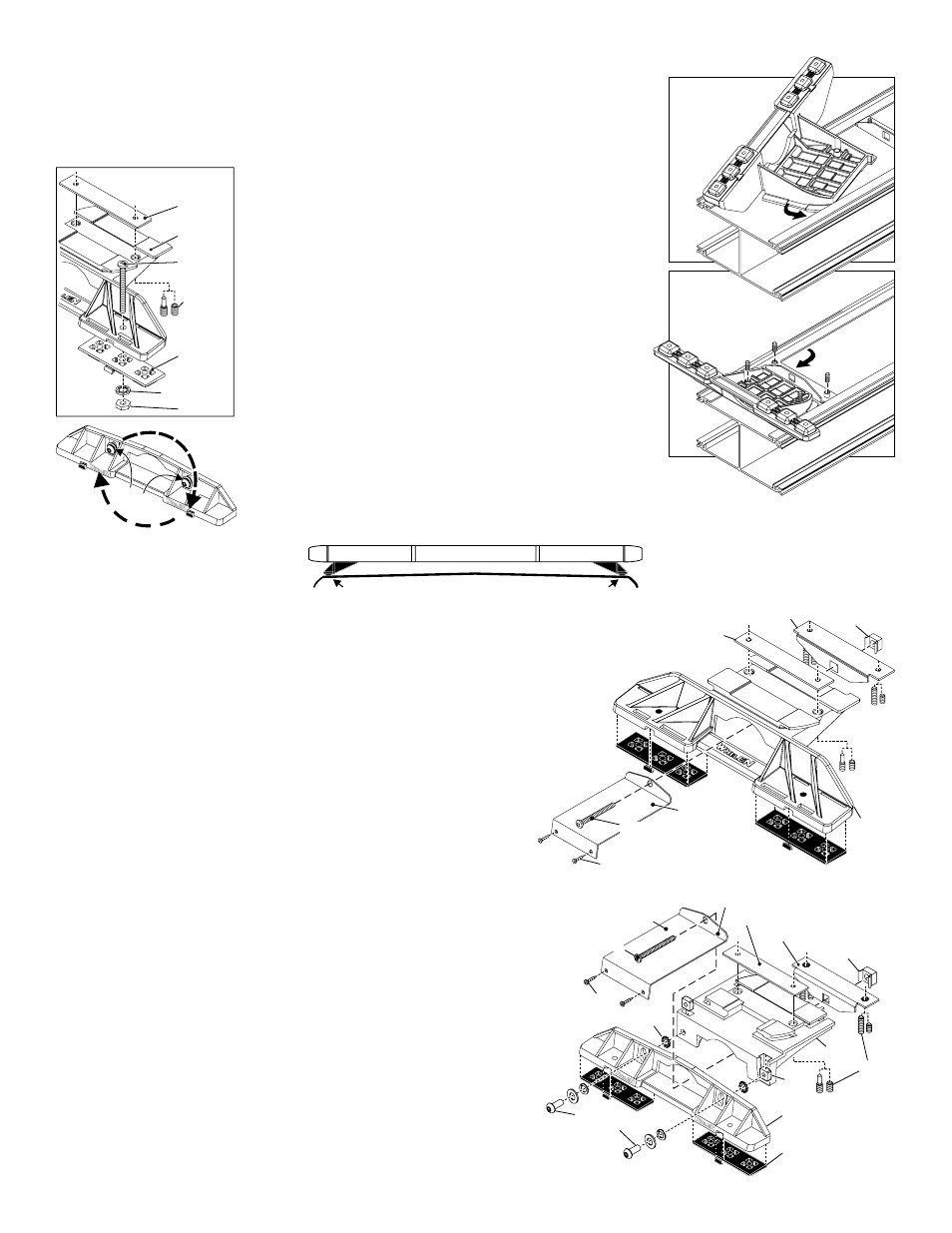
Fig.1
IMPORTANT! The lightbar should be a minimum of 16" from any radio antennas!
Permanent Mounting:
1.
Locate the mounting foot and locking plate included with your lightbar. If not already present, install the locking plate
onto the mounting foot using the supplied allen screws. MKAJ: On the adjustable mounting foot, you must first
drill the hole in the foot, that is mentioned here in step 6. Use the hole in the mounting pad as a guide.
2.
Flip the lightbar upside-down to expose the bottom of the extrusion and place the mounting foot onto the extrusion.
3.
Rotate the mounting foot 90° counter-clockwise. Make sure that the edges of
the foot slide under the extrusion mounting lip (See illustrations A & B).
Repeat this procedure for the remaining mounting foot and return the lightbar
to its right side-up position.
4.
Position the lightbar onto the vehicle roof in the desired mounting location.
One often selected location is directly above the Bpillars. This area is the
strongest part of the roof. Refer to your lightbar manual for cable exit location,
to be sure that the lightbar is facing the proper direction.
5.
Adjust the two feet outwards so that they are as close to the edge of the roof
as possible (See below). Make sure that both mounting feet are in full contact
with the roof and that there is no less than 1/2” clearance between roof and
lightbar. When the mounting feet are in position, carefully tighten the locking
plate allen head set screws.
6.
With the lightbar in its exact mounting position, use the hole in the mounting
foot as a guide and mark the mounting hole location off onto the mounting
surface.
7.
Remove the lightbar and drill the mounting holes you marked off in step 6.
8.
Place the lightbar back onto the vehicle lined up with the mounting holes and
secure it to the vehicle using the supplied hardware.
NOTE: Model MKAJ is an adjustable mounting foot. On this model you may
loosen the screws on the rear of the foot and adjust the angle of the lightbar.
This feature can be used if the angle of the roof is not level with the road.
IMPORTANT: To adjust the leveling screws, use a torque wrench set at 35 to
40 in./lbs.
Strap Mounting:
1.
Locate the mounting foot, anchor plate and locking plate included with your lightbar. If not
already present, install the locking plate onto the mounting foot using the supplied allen set
screws.
2.
Flip the lightbar upside-down to expose the bottom of the extrusion and place the mounting
foot onto the extrusion (See illustrations A & B above).
3.
Rotate the foot 90° counter-clockwise. Make sure that the edges of the foot slide under the
extrusion mounting lip. Install an anchor plate onto the extrusion in the same manner.
4.
Repeat this procedure for the remaining mounting foot and anchor plate and return the
lightbar to its right side-up position.
5.
Position the lightbar onto the vehicle roof in the desired mounting location. One often
selected location is directly above the B-pillars. This area is the strongest part of the roof.
Refer to your lightbar manual for cable exit location, to be sure that the lightbar is facing the
proper direction.
6.
Adjust the two mounting feet outwards so that they are as close to the edge of the roof as
possible. Both mounting feet must be in full contact with the roof. Be sure that there is no less
than 1/2” clearance between roof and lightbar (See above). When the mounting feet are in
position, carefully tighten the locking plate allen set screws.
7.
Return the lightbar to an upside-down position. Slide each anchor plate outwards until it is
fully engaged with its corresponding mounting foot. With the mounting feet and anchor plates
in position, firmly tighten all of the allen set screws (2 or 4 per side). Flip the lightbar over and
return it to its mounting position.
8.
Open both drivers side doors. In the area directly below the mounting foot, pull the weather-
strip away from the vehicle so the area where the mounting strap will be secured is exposed.
Repeat for the other side.
9.
Insert the mounting strap through the mounting foot. Be sure that the strap fits flush against
the area where it will be secured onto the vehicle. Insert the tension bolt through the
mounting strap and anchor plate, into the tinnerman nut. Tighten slightly with a long-shafted,
Phillips screwdriver. Repeat procedure for passenger side.
10.
If your mounting strap has mounting holes on the end of the strap, use these holes as a
template to drill appropriately sized pilot holes through the strap and into the vehicle. Secure
the strap to the vehicle with the supplied mounting screws. Repeat steps 8 - 10 for the
passenger side of the vehicle.
11.
Firmly tighten the tension bolts to secure lightbar to vehicle.
B.
with the l
he anchor plate is
used for strap mounting
Loosely secure
foot
ocking
late
.
B.
B.
B.
p
. T
A.
Twist mounting foot into
position, under lip
A.
ANCHOR PLATE
(strap mounting only)
NOTE: Unless otherwise specified, the lightbar mounting
feet must be sitting as close to the edge of the roof as
possible. Mounting feet must be in full contact with the
roof and not be hanging off the edge.
For strap mounted lightbars, be sure you have the right
sized bar for your vehicle. The bar should be about the
same width as the vehicle roof. If the bar is too large or
small it will not mount properly to the vehicle and may
shift or come loose during driving.
1/2" Minimum Clearance at Closest Point
Vehicle Roof