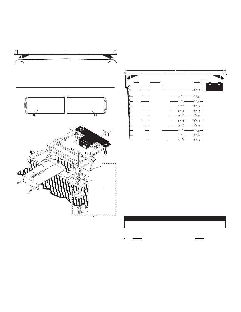
Fig. 1, Permanent mounting, Strap mounting – Whelen CE4AAAA User Manual
Page 2: Wiring and operation, Low power, Scan-lock
Page 2
1/4 - 20 X 1-1/2" PPHMS
1/4 - 20 X 7/16" HEX NUT
SET SCREW
MOUNTING
FOOT
ANCHOR
PLATE
NOTE: Mounting foot and anchor
Plate both Slide into extrusion
SET SCREW (2)
STRAP MOUNTING
(optional)
PERMANENT MOUNTING
Fig. 1
TINNERMAN
NUT
MOUNTING SURF
ACE
MOUNTING SURF
ACE
MOUNTING SURF
ACE
Mounting Screw
(to vehicle)
MOUNTING PAD
MOUNTING PAD
NOTE: All mounting pads
are left intact for strap
mounting.
NOTE: All mounting pads
are left intact for strap
mounting.
NOTE: All mounting pads
are left intact for strap
mounting.
1/4 INTERNAL TOOTH
LOCK WASHER
1/4 - 20 X 7/16" HEX NUT
1/4 INTERNAL TOOTH
LOCK WASHER
1/4 INTERNAL TOOTH
LOCK WASHER
1/4 INTERNAL TOOTH
LOCK WASHER
Tension
Bolt
Tension
Bolt
Tension
Bolt
MOUNTING
STRAP
MOUNTING
STRAP
MOUNTING
STRAP
DRILLING THE CABLE ACCESS HOLE
For
cables exiting
the Driver-side
of the extrusion
lightbars
with
For
cables exiting
the Passenger-side
of the extrusion
lightbars
with
FRONT OF LIGHTBAR
FRONT OF LIGHTBAR
FRONT OF LIGHTBAR
Important: The lightbar should be a minimum of 16”
from any radio antennas!
Caution:
Permanent mounting of this product will require drilling.
It is absolutely necessary to make sure that no other vehicle
components could be damaged by this process. Check both sides of
the mounting surface before starting. If damage is likely, select a
different mounting location.
Permanent Mounting:
1.
Once you determine the mounting location for your lightbar, remove either the
two outer or inner rubber mounting pads from the mounting foot. Carefully
remove the mounting pad’s guide dart so that the hole through the center of the
pad is exposed.
2.
Place the lightbar into its exact mounting location and mark the mounting hole
locations onto the mounting surface. Use the holes in the mounting feet as a
template.
3.
Remove the lightbar and drill the mounting holes with a 1/4” drill. Also drill a 1/
2” wire exit hole (see above). It is recommended you install a rubber grommet
(customer supplied) into the wire exit hole
4.
Position the mounting pad between the mounting foot and the mounting
surface on each end of the lightbar.
5.
Insert the mounting bolt through the mounting foot, hardware and mounting
surface as shown above.
6.
Repeat for remaining bolts and tighten all hardware.
Strap Mounting:
Strap mounting uses a mounting strap which is purchased seperately and is avail-
able for most vehicles. This strap attaches to the mounting foot as shown in fig. 1 and
is secured to the vehicle with 2 sheet metal screws.
Wiring and Operation:
The lightbar is controlled through the control cable which should be connected to a
customer supplied switch box. Wire functions and fusing are shown in the wiring
diagram.
WARNING! All customer supplied wires that connect to the positive
terminal of the battery must be sized to supply at least 125% of the
maximum operating current and FUSED at the battery to carry that
load. DO NOT USE CIRCUIT BREAKERS WITH THIS PRODUCT!
Low Power:
Applying +12 volts DC to the Violet wire for more than 1 second holds the lightbar in
low power mode until that voltage is removed. A toggle switch is best suited for this.
Scan-Lock™:
To operate Scan-Lock™, switch the lightbar on and activate the control wire of the
function that requires flash pattern selection.
TO CHANGE PATTERNS: To cycle forward apply +12 VDC to the WHT/VIO wire for
less than 1 second and release. To cycle back to the previous pattern apply +12 VDC
to WHT/VIO wire for over 1 second.
TO CHANGE THE DEFAULT PATTERN: When the desired pattern is displayed,
allow it to run for more than 5 seconds. The lighthead will now display this pattern
when initially activated.
TO RESTORE THE FACTORY DEFAULT PATTERN: With power off, apply +12
VDC to the WHT/VIO wire. While continuing to apply power to Scan-Lock™ turn
lighthead(s) on. The factory default pattern will be displayed.
A normally open momentary switch is best suited for this.
BLACK
RED
GREEN
BLUE
WHITE
YELLOW
WHT/BLK
VIOLET
WHT/BLU
WHT/YEL
WHT/GRN
WHT/VIO
(+) Front Warning
(+) Rear Warning
(+) Driver Alley
(+) Passngr Alley
(+) Take Downs
(+) Low Power
(+) TA Flashers
(+) Left TA
(+) Right TA
(+) Scan-Lock
(-) Ground
(+) Positive
Wire
Function
Fuse
20 Amp
1 Amp
1 Amp
1 Amp
1 Amp
1 Amp
1 Amp
1 Amp
1 Amp
1 Amp
All fuses and
switches are
c u s t o m e r
supplied
BATTERY
SPST Switches
Momentary Switch
Wiring Diagram
Flashing Take-Down and Alley Light Patterns:
#
Pattern
Lamps
1. . . . .SingleFlash 240 . . . . . . . . . . . . . . . . . . . . . . . . . . . .Take-Down & Alley Lights
2. . . . .DoubleFlash 120 . . . . . . . . . . . . . . . . . . . . . . . . . . .Take-Down & Alley Lights
3. . . . .SingleFlash 240 . . . . . . . . . . . . . . . . . . . . . . . . . . . .Take-Down Only
4. . . . .DoubleFlash 120 . . . . . . . . . . . . . . . . . . . . . . . . . . .Take-Down Only
5. . . . .SingleFlash 240 . . . . . . . . . . . . . . . . . . . . . . . . . . . .Alley Lights
6. . . . .DoubleFlash 120 . . . . . . . . . . . . . . . . . . . . . . . . . . .Alley Lights
7. . . . .OFF
Lightbar Patterns:
1.
ActionScan™
2.
SignalAlert™
3.
CometFlash®
4.
DoubleFlash 75
5.
SingleFlash 75
6.
LongBurst™75
7.
SingleFlash 60
8.
SingleFlash 90
9.
SingleFlash 120
10.
SingleFlash 300
11.
DoubleFlash 120
12.
ActionFlash™75
13.
ActionFlash™150
14.
PingPong™75
15.
FlimFlam™
16.
ModuFlash™
17.
Off
CAUTION! DO NOT LOOK DIRECTLY AT THESE LED’S WHILE THEY ARE ON.
MOMENTARY BLINDNESS AND/OR EYE DAMAGE COULD RESULT!
I M P O R TA N T W A R N I N G !
1/2" Minimum Clearance at Closest Point
NOTE:
Unless otherwise specified, the lightbar mounting feet must be
sitting as close to the edge of the roof as possible. Mounting feet must
also be in full contact with the roof and not be hanging off the edge.
Be sure you have the right sized lightbar for your vehicle. The lightbar
should be approximately the same width as the vehicle roof. If the
lightbar is too large or small it will not mount properly to the vehicle
and may shift or come loose during driving.