5" mounting foot, Routing your edge® lightbar cable(s), Page 3 – Whelen 9M140W00 User Manual
Page 3
Page 3
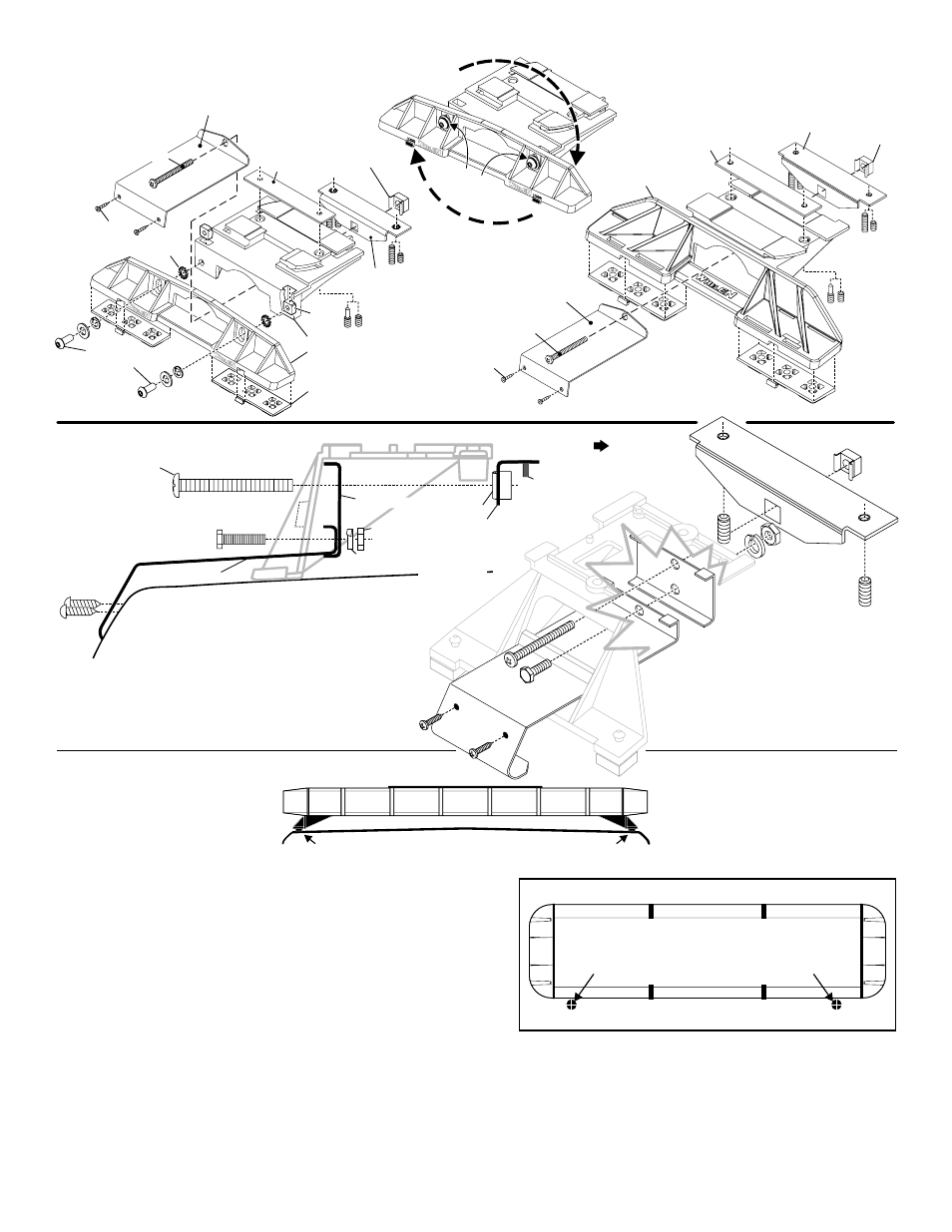
MOUNTING FOOT
TINNERMAN
NUT
FOOT
ANCHOR
PLATE
SET
SCREW
Plate slides into
lightbar extrusion
5" Mounting Foot
NUT
BOLT
SPLIT LOCK
WASHER
METAL SCREW
NOTE: The mounting straps are made to fit the contours of individual
vehicles. The strap
may look different. If your lightbar has a 5"
mounting foot, it will assemble differently than the standard
mounting foot. It also uses an extension to compensate for
the extra height. Follow these illustrations for assembly.
Mounting to the lightbar is the same.
shown here is for example only. The strap
for your vehicle
NOTE:
NOTE:
NOTE:
NOTE:
NOTE:
NOTE:
STRAP
S H E E T
M E T A L
SCREWS
EXTENSION
VEHICLE ROOF
Locking
Plate
Mounting
Foot
Nut
Mounting
Pad
Adjustment
screws
Lock
Washer
Anchor
Plate
Tinnerman
Nut
Tinnerman
Nut
Anchor
Plate
Locking
Plate
Mounting
Strap
Mounting
Screw
Adjustable Mounting Foot / Model MKAJ
Standard Mounting Foot / Model MKEZ
Tighten
screw
s
with
torque
wrench
set
at 35
to 40
in/lbs
Mounting
Strap
Mounting
Screw
Tension
Bolt
Tension
Bolt
Model
MKAJ
Mounting
Foot
NOTE: Unless otherwise specified, the
lightbar mounting feet must be sitting as
close to the edge of the roof as possible.
Mounting feet must also be in full contact
with the roof and not be hanging off
the edge.
IMPORTANT: For strap mounted bars, be sure you have the right
sized lightbar for your vehicle. The lightbar should be about the
same width as the vehicle roof. If the
lightbar is too large or small it will not
mount properly to the vehicle and
may shift or come loose during driving.
1/2" Minimum Clearance at Closest Point
Routing your Edge® Lightbar Cable(s)
1.
To protect the headliner from damage caused by drilling the cable access
hole through the vehicle roof, allow a 5” to 7” distance between roof and
headliner by lowering the headliner before drilling.
2.
Using a 1” hole saw, drill the cable access hole.
NOTE:There may be a roof support member that spans the distance between
the driver’s and passenger’s side. DO NOT DRILL THROUGH THIS MEMBER!
Adjust the location until the hole can be drilled without contacting this
support member.
3.
Use a round file to smooth and de-burr the edges of the hole.
4.
Insert a 1” grommet (user supplied) into the cable access hole.
5.
Insert the cable through the cable access hole into the vehicle. Use RTV silicone to weatherproof the access hole after the cable are pulled
completely into the vehicle.
6.
Route the cable to your switch box. It is left to the installation technician’s discretion to select a path for this cable that will both protect the cable from
possible damage and not interfere with the operation of any other vehicle components or equipment. Refer to the instructions included with your
switches for switch wiring information.
DRILLING THE CABLE ACCESS HOLE
Drill cable access hole in appropriate area
for your lightbar (see note)
FRONT OF LIGHTBAR
For
cables exiting
the Driver-side
of the extrusion
lightbars
with
For
cables exiting
the Passenger-side
of the extrusion
lightbars
with