Servicin our li htbar g y g – Whelen SL0TAAAA User Manual
Page 2
Page 2
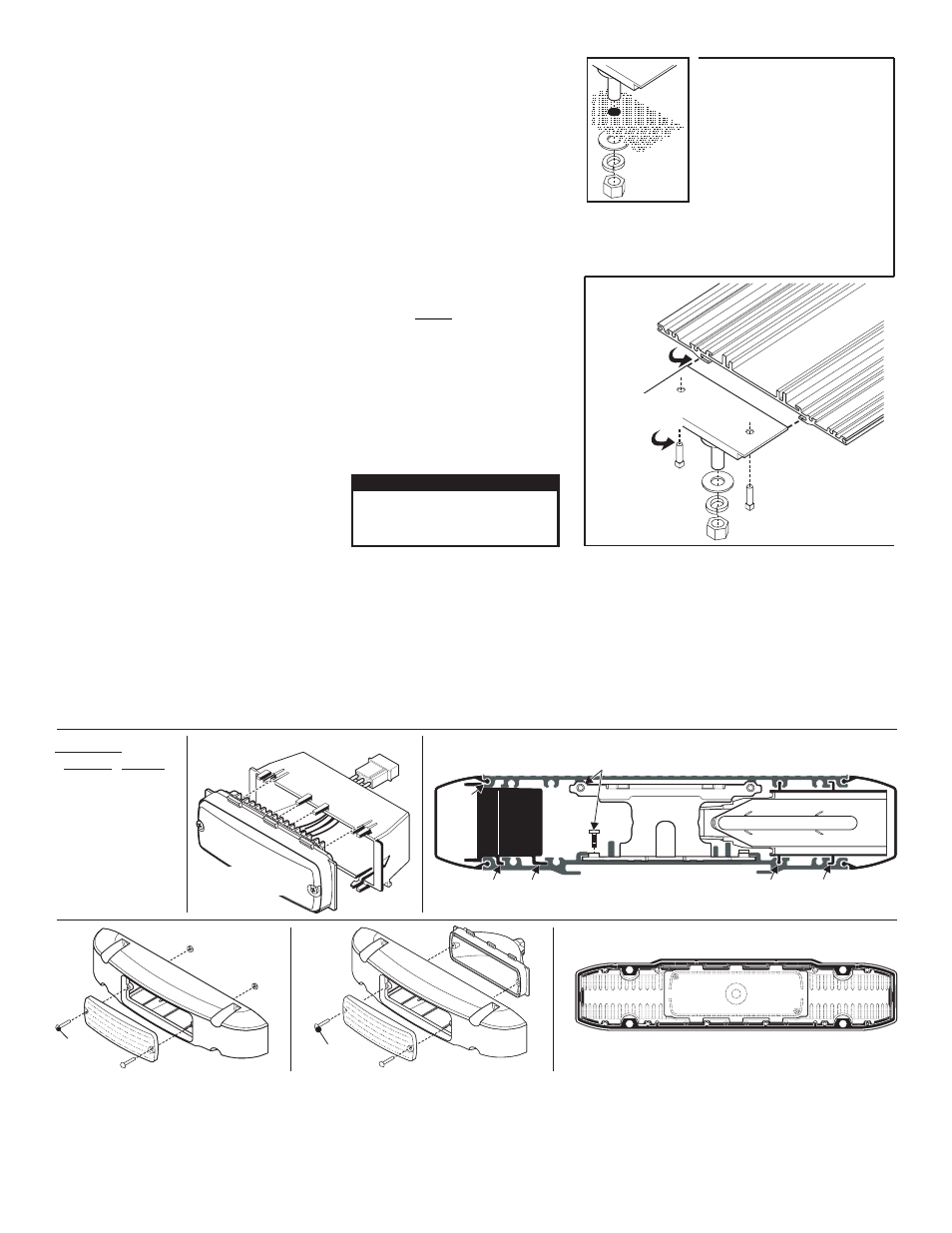
Slide Bolt
Mounting
Mounting
Surface
Mounting
Surface
Mounting
Surface
Insert slide bolts into base,
slide them across to their mounting
position and secure with set screws.
2.
1. Remove one lightbar endcap.
Fig. 1 Slide Bolt Mount:
-
Drill the four holes with an appropriately sized drill bit.
4.
Replace end cap and insert bolts into their 4 mounting
holes and secure the lightbar with supplied hardware.
5.
Position the lightbar onto the
vehicle and mark the four bolt hole
locations on the mounting surface.
3.
Slide bolt slides
into base here.
Tighten both set
screws to secure
slide bolt to base.
Fig. 1a Inserting
Slide Bolt into
Base.
IMPORTANT! The lightbar should be a minimum of 16" from any radio antennas!
Mounting your Lightbar:
This lightbar mounts with 4 bolts affixed to mounting plates that slide into the track on the bottom of the
lighbar base. Figures 1 and 1a show how the slide bolt assembly slides into your lightbars base and mounts
onto the vehicle. Use an appropriately sized drill bit sized for a 1/2 - #13 X 2” bolt, to drill the mounting
holes. When securing the slide bolts to the bottom of the lightbar base, be sure the outside bolts are spaced
far enough apart and near enough to the ends of the vehicle roof.
Lightbar Cables:
This lightbar uses a 3-conductor cable for LEDs, a 6 conductor cable for HALOGEN and a 4-conductor
cable for BRAKE/TAIL lights. Extend the 3- and 6-conductor cables towards your switch panel. The
instructions included with your switches will provide switch wiring information. The 4-conductor cable
connects to your brake light. There are also 2 wires for Scan-Lock™ (flash pattern selection).
Refer to the parts illustration on the next page for wire designations and fusing
.
WARNING! All Customer supplied wires that connect to the positive terminal of the battery must be
sized to supply at least 125% of the maximum operating current and FUSED at the battery to carry
that load. DO NOT USE CIRCUIT BREAKERS WITH THIS PRODUCT!
Scan-Lock™
In the Scan-Lock™ cable the RED wire controls the front LEDs and the GREEN wire controls the rear
LEDs. The LEDs must be on for flash pattern selection.
TO CHANGE PATTERNS: Apply +12 volts to the Scan-Lock™ wire for less than 1 second and release to
cycle forward to the next available pattern. Apply +12 volts to the the Scan-Lock™ wire for more than 1
second and release to cycle back to the previous pattern.
TO CHANGE THE DEFAULT PATTERN: When the
desired pattern is displayed, allow it to run for more than 5
seconds. The lighthead will now display this pattern when
initially activated.
TO RESTORE THE FACTORY DEFAULT PATTERN:
Apply +12 volts to the Scan-Lock™ wire. With Scan-
Lock™ activated, turn power to the lighthead on. The
factory default pattern will now be displayed.
A normally open momentary switch can be used to control Scan-Lock operation.
CAUTION! DO NOT LOOK DIRECTLY AT
THESE LEDS WHILE THEY ARE ON.
MOMENTARY BLINDNESS AND/OR EYE
DAMAGE COULD RESULT!
IMPORTANT WARNING!
Available Flash Patterns:
1C: SignalAlert™ 3 cycles of 1A and 3 cycles of 1S
1A: SignalAlert™ 1 Alternates with 2
1S: SignalAlert™ 1 & 2 Simultaneous
2A: CometFlash® 1 Alternates with 2
2S: CometFlash® 1 & 2 Simultaneous
2C: CometFlash® 3 cycles of 2A and 3 cycles of 2S
3A: DoubleFlash 1 Alternates with 2
3S: DoubleFlash 1 & 2 Simultaneous
3C: DoubleFlash 3 cycles of 3A and 3 cycles of 3S
4A: SingleFlash 1 Alternates with 2
4S: SingleFlash 1 & 2 Simultaneous
4C: SingleFlash 3 cycles of 4A and 3 cycles of 4S
5: SteadyFlash 1 & 2 Steady / 3 & 4 SingleFlash / SIM
6: Steady 1, 2, 3 & 4 Steady
Steady: Full power 1 second, then slow ramp to 40
Without
Alley
Light
With
Alley
Light
#6 x 5/8" PPH
PLAST-LOC
#6-32 x 5/8"
PPHMS
#6-32 ELASTIC
STOP NUT
Place the endcap gasket onto the endcap matching up all the tabs and holes.
Endcap: Lighthead and Gasket
Servicin
our Li htbar
g
y
g
Installing Corner Linear-LED®
Lighthead into extrusion
Insert the tabs on the lighthead housing,
into the channels in the extrusion.
Insert the tabs on the lighthead housing,
into the channels in the extrusion.
Installing Lens and Lighthead
Housing into extrusion
Lens
fits
here
Top and bottom of extrusion
secure to Support Bracket.
SUPPORT
BRACKET
Installing a lighthead
into its housing
Use the illustrations
shown if you need to
gain access to the
lightbar to service or
replace parts.