Important warning – Whelen FL0TAAAA User Manual
Page 2
Page 2
Mounting your Lightbar:
Permanent mounting of this product will require drilling. It is absolutely necessary
to make sure that no other vehicle components could be damaged by this process.
Check both sides of the mounting surface before starting. If damage is likely, select
a different mounting location.
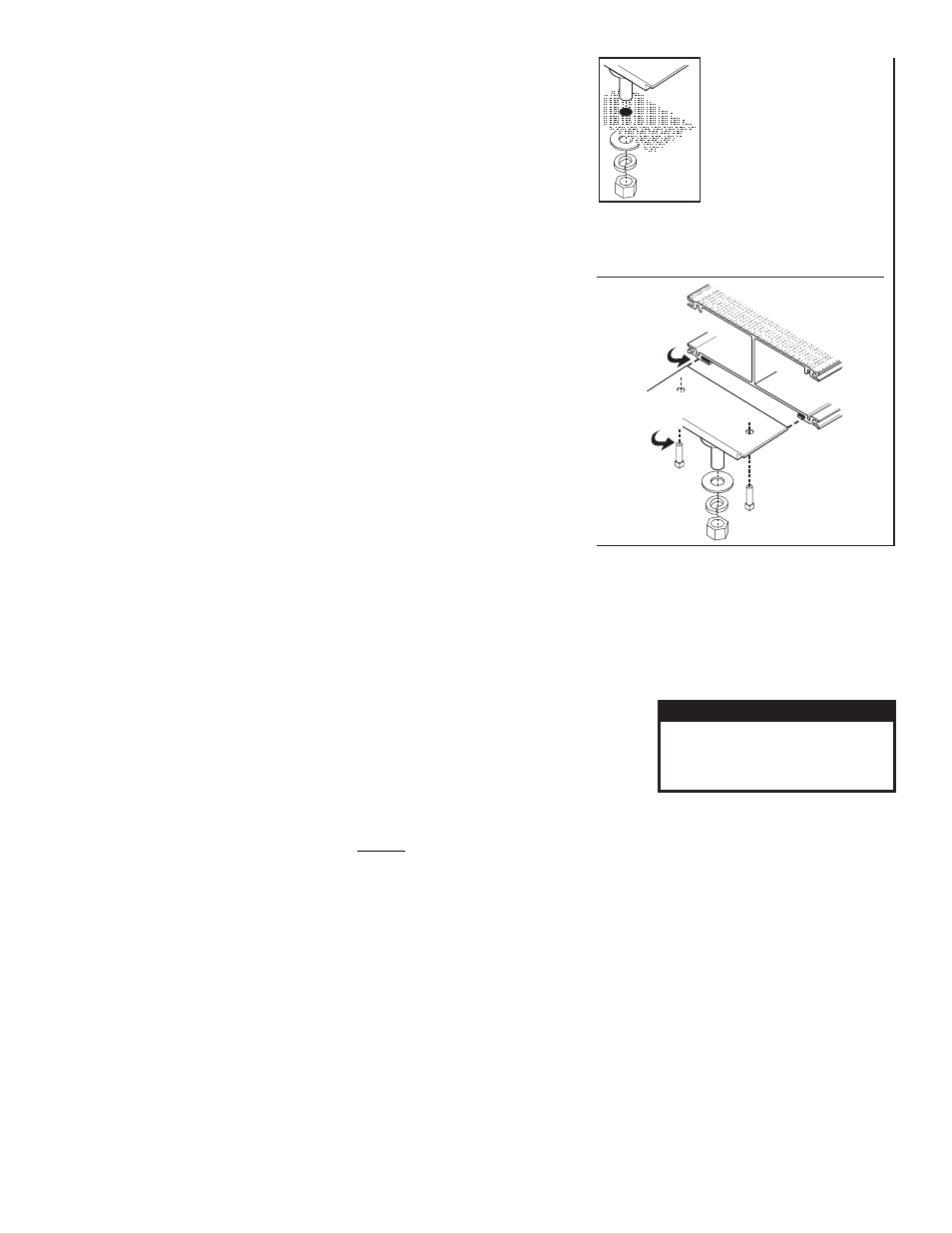
This lightbar mounts with 3 bolts, affixed to mounting plates that slide into the track on the
bottom of the lightbar base. Figures 1 and 1a show how the slide bolt assembly slides into
your lightbars base and mounts onto the vehicle. Use an appropriately sized drill bit sized
for a 1/2 - 13 X 2” bolt, to drill the mounting holes. When you secure the slide bolts to the
bottom of the lightbar base, be sure the outside bolts are spaced far enough apart and
near enough to the ends of the vehicle roof.
Operation:
Operation of the function wires in the cables exiting the lightbar is outlined below.
Applying +12 volts DC to these wires will activate their function. Refer to the parts
illustration for fusing information. Any unused wire should be capped off.
LED CABLE:
GREEN: Activates the FRONT LED’s.
3 conductor
WHITE: Activates the REAR LED’s.
TAKEDOWN/ALLEY:
6 conductor:
WHITE: Activates (Steady) TAKEDOWNS and WORKLIGHTS
GREEN: Activates the PASSENGER SIDE ALLEY LIGHTS
RED: Activates the DRIVER SIDE ALLEY LIGHTS
BLUE: Activates the TAKEDOWNS in FLASH MODE
BRAKE-TAIL:
WHITE: Activates the TAIL LIGHTS
4 conductor
GREEN: Activates the PASSENGER SIDE BRAKE LIGHT
RED: Activates the DRIVER SIDE BRAKE LIGHT
SCANLOCK:
RED: Scan-Lock™ Flash pattern selection for the FRONT LED’s
3 conductor
GREEN: Scan-Lock™ Flash pattern selection for the REAR LED’s
Scan-Lock™ / Flash Pattern Selection:
The RED wire is the Scan-Lock™ wire for FRONT LED’s. The GREEN wire is the Scan-Lock™ wire for REAR LED’s. LED’s must be on
for Scan-Lock™ to work.
TO CHANGE PATTERNS: To cycle forward to the next pattern: Apply +VBAT to the “Scan-Lock™ wire for less than 1 second and
release. To cycle back to the previous pattern: Apply +VBAT to the Scan-Lock™ wire for more than 1 second and release.
TO CHANGE THE DEFAULT PATTERN: When the desired pattern is active, allow it to run for
more than 5 seconds. The lighthead will now display this pattern when activated.
TO RESTORE THE FACTORY DEFAULT PATTERN: With power to the lightheads off, apply
+VBAT to the Scan-Lock™ wire. While still applying +VBAT to the “Scan-Lock™ wire, turn
power to the lightheads back on. The factory default pattern should now be displayed.
A Normally Open momentary switch can be used to control Scan-Lock™
WARNING! All Customer supplied wires that connect to the positive terminal of the battery must be sized to supply at least
125% of the maximum operating current and FUSED at the battery to carry that load. DO NOT USE CIRCUIT BREAKERS WITH
THIS PRODUCT!
IMPORTANT! It is the responsibility of the installation technician to make sure that the installation and operation of this product
will not interfere with or compromise the operation or efficiency of any vehicle equipment! Before returning the vehicle to
active service, visually confirm the proper operation of this product, as well as all vehicle components/equipment.
CAUTION! DO NOT LOOK DIRECTLY AT
THESE LED’S WHILE THEY ARE ON.
MOMENTARY BLINDNESS AND/OR EYE
DAMAGE COULD RESULT!
IMPORTANT WARNING!
Available Flash Patterns:
1. SignalAlert™ 3 cycles of 1A and 3 cycles of 1S
2. SignalAlert™ 1 Alternates with 2
3. SignalAlert™ 1 & 2 Simultaneous
4. CometFlash® 1 Alternates with 2
5. CometFlash® 1 & 2 Simultaneous
6. CometFlash® 3 cycles of 2A and 3 cycles of 2S
7. DoubleFlash 1 Alternates with 2
8. DoubleFlash 1 & 2 Simultaneous
9. DoubleFlash 3 cycles of 3A and 3 cycles of 3S
10. 10.SingleFlash 1 Alternates with 2
11. SingleFlash 1 & 2 Simultaneous
12. SingleFlash 3 cycles of 4A and 3 cycles of 4S
13. SteadyFlash 1 & 2 Steady / 3 & 4 SingleFlash
14. Steady 1, 2, 3 & 4 Steady
15. Steady: Full power 1 sec., then slow ramp to 40
Slide bolt slides
into the base here.
Tighten both set
screws to secure
slide bolt to base
Fig. 1a Inserting
Slide Bolt into
Base
Slide Bolt
Mounting
Mounting
Surface
Mounting
Surface
Mounting
Surface
Insert slide bolts into base,
slide them across to their mounting
position and secure with set screws
2.
1. Remove one lightbar endcap.
Fig. 1 Slide Bolt Mount:
/
Drill the four holes with an appropriately sized drill bit
4.
Replace end cap and insert bolts into their 4 mounting
holes and secure the lightbar with supplied hardware
5.
Position the lightbar onto the
vehicle and mark the four bolt hole
locations on the mounting surface
3.