Permanent mounting / stud mount – Whelen CW0BAAAA User Manual
Page 2
Page 2
WHT
RED
GRN
BLACK
RED
RED/WHT
BLK
BLK/WHT
BLK
BLUE
WHITE
GREEN
ORANGE
RED
(+) TAIL LIGHT
(+) LEFT TURN
(+) RIGHT TURN
(-) GROUND
(+) FRONT LEDS
(+) REAR LEDS
(-) FRONT LEDS
(-) REAR LEDS
GROUND
LOW POWER
(+) WORKLIGHT
(+) PATTERN OVERIDE
(+) AUX / UNUSED
(+) SCANLOCK
Wire
Function
BRAKE-TAIL-TURN
Fuse
10 Amp
10 Amp
5 Amp
1 Amp
1 Amp
1 Amp
All fuses and
switches are
c u s t o m e r
supplied
BATTERY
SPST Switches
SPST Switches
Momentary Switch
Century Wrecker Lightbar
WHT (-) GND
BRN (+) TAIL
YEL (+) TURN
WHT (-) GND
BRN (+) TAIL
YEL (+) TURN
RIGHT - BRAKE
TAIL
TURN LIGHT
LEFT - BRAKE
TAIL
TURN LIGHT
TO GROUND (BLK)
TO TAIL (WHT)
TO LEFT TURN (RED)
TO GROUND (BLK)
TO TAIL (WHT)
TO RIGHT TURN (GRN)
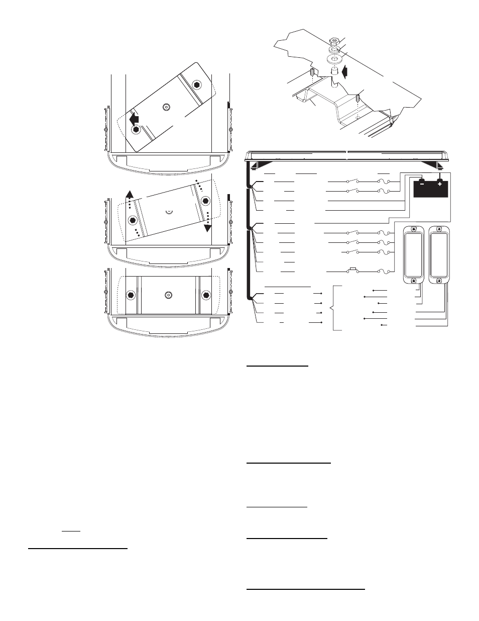
IMPORTANT! The lightbar should be a minimum
of 16" from any radio antennas!
Permanent Mounting / Stud Mount:
Caution: Permanent
mounting of this product
will require drilling. Be
absolutely sure that no
other vehicle
components could be
damaged by this
process. Check both
sides of the mounting
surface before starting. If
damage is likely, select a
different mounting
location.
1.
Insert the 2 Stud
Mount brackets under
the lip in the bottom of
the extrusion.
(rounded end first)
and pivot the bracket
so that the other end
slides under the other
lip in the extrusion.
2.
Make sure that the
brackets are sitting all
the way at each end
of the extrusion, then
secure them with the
supplied allen set
screws.
3.
Place the lightbar in
the exact mounting
location. Mark the
location of the 2
mounting holes onto
the mounting surface,
and the area for the
wire passage hole.
This hole should be
located directly below where the wires exit the extrusion.
4.
Remove the lightbar and drill the mounting holes as well as the 5/16” dia.
wire passage hole. De-burr all the holes and install a rubber grommet
(customer supplied) into the wire passage hole.
5.
Route the wires through the grommet and to the necessary switches and
power source as shown in the wiring diagram.
6.
Secure the lightbar to the vehicle using the hardware provided. From the
underside of the mounting surface, apply RTV around each mounting
hole and the grommeted wire passage hole.
IMPORTANT! It is the responsibility of the installation technician to make
sure that the installation and operation of this product will not interfere
with or compromise the operation or efficiency of any vehicle equipment!
Before returning the vehicle to active service, visually confirm the proper
operation of this product, as well as all vehicle components/equipment.
Lightbar Cables:
This lightbar uses a 4-conductor cable for LEDs and a 6 conductor cable for options.
There is also a 4 conductor cable for BRAKE-TAIL to connect to your brake lights.
Extend the 4 and 6 conductor LED and FUNCTION cables towards your switch
panel. The instructions included with your switches will provide switch wiring
information. The BRAKE-TAIL cable connects to the brake lights.
WARNING! All Customer supplied wires that connect to the positive terminal of
the battery must be sized to supply at least 125% of the maximum operating
current and FUSED at the battery to carry that load. DO NOT USE CIRCUIT
BREAKERS WITH THIS PRODUCT!
6 Conductor Option Cable:
WHITE:
Apply +12 volts to activate the Worklight
GREEN:
Apply +12 volts to activate Pattern Override
RED:
Apply +12 volts to activate Scan-Lock™
BLUE:
Apply +12 volts to activate Low Power
.
ORG:
Available to add option / + 12 volts to activate / Fuse appropriately
BLACK:
Ground
RED: Scan-Lock™
LED’s must be on for Scan-Lock™ to work.
TO CHANGE PATTERNS: To cycle forward to the next available pattern: Apply +12
volts to the RED wire for less than 1 second and release. To cycle back to the
previous pattern: Apply +12 volts to the RED wire for over 1 second and release.
TO CHANGE THE DEFAULT PATTERN: Allow the desired pattern to run for more
than 5 seconds. The lighthead will now display this pattern when activated.
TO RESTORE THE FACTORY DEFAULT PATTERN: With power to the lightheads
off, apply +12 volts to the RED wire. While still applying +12 volts to the RED wire,
turn power to the lightheads back on and the factory default pattern will be displayed.
A normally open momentary switch can be used to control Scan-Lock™.
GREEN: Pattern Override
Applying +12 volts to the GREEN wire while lightheads are activated will change the
flash pattern to whatever “pattern override” is programmed for. To program the flash
pattern activate the lightbar. Activate pattern override by applying +12 volts to the
GREEN wire then select a flash pattern using the Scan-Lock™ procedure.
BLUE: Low Power
Applying +12 volts DC to the BLUE wire for more than 1 second holds the lightbar in
low power mode until that voltage is removed. A toggle switch is best suited for this.
4 Conductor LED Cable:
RED:
Apply +12 volts to activate the Front LED’s
RED/WHT:
Apply +12 volts to activate the Rear LED’s
BLACK:
Ground wire for Front LED’s
BLK/WHT:
Ground wire for Rear LED’s
4 Conductor Brake-Tail-Turn Cable:
Connect as shown above.
3/8" FLAT WASHER (1)
1/4 - 20 X 1/2
ALLEN SET
SCREW (1)
STUD MOUNT
BRACKET (1)
STUD MOUNT
MOUNTING
SURFACE
3/8"
mounting
hole
3/8" SPLIT LOCK WASHER (1)
3/8 - 16 HEX NUT (1)
Secure bracket with
allen set screws
Insert rounded end
under lip in extrusion
Swing opposite end
under other lip