Fig. 5, Fig. 7, Fig. 8 – Whelen 45B52 User Manual
Page 3: Fig. 6, Installing options into extrusion, Halogen, strobe or led lighthead, Corner strobe / removal, Corner strobe / installation
Page 3
CORNER
S T R O B E
SUPPORT
BRACKET
S C R E W , # 6
X 3/8" PPHSMS
LIGHTHEAD
TAB
#6 FASTEX SCREW GROMMETS
(Install into lightbar base)
END
OF
LIGHTBAR
Bracket
slides
into
lightbar
LIGHTBAR BASE
Fastex
grommet
Clips snap over
edge of lighthead.
CORNER STROBE
Snap Lighthead mtg. holes
onto bosses on bracket.
Snap Lighthead mtg. holes
onto bosses on bracket.
B
C
Fig. 5
A
Snap Lighthead mtg. holes
onto bosses on bracket.
Fig. 7
Load
Light
Mounting
B ra
c k
e t
Slide
grommets
into base
A Single light MR11
bracket (each side) is
mounted in the single
and the center hole of
the bottom 3 holes.
A Double light MR11
bracket (center mount)
is mounted in the single
and center hole of
the top 3 holes.
SIDE VIEW
OF BRACKET
Front
Single hole
400 Linear Split LED with MR11 Load Light / TA only
Fig. 8
Side view / Base Extrusion
Housing
s n a p s
into base
extrusion
Housing
i s t h e n
secured
to base
u s i n g
supplied
s c r e w s
Halogen, Strobe or LED
Lighthead
(New style housing)
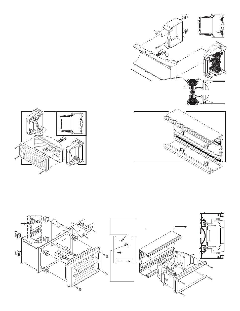
3. Now pull the clips back on the mounting bracket that secure the lighthead as
you lift the lighthead off of the raised bosses on the bracket (Fig. 4).
4. Being careful not to pull out any wires, lift the lighthead out of the lightbar base,
disconnect its connector from the lightbar wiring harness, then lift the lighthead out
of the lightbar.
5. To reinstall the lighthead, plug the lightheads connector into the lightbar, snap
it back into the brackets and replace any lenses or lenscaps you removed.
Corner Strobe / Removal:
1. Disconnect the lightbar from it’s power source and remove the endcap in front of
the lighthead you wish to replace or service (See strobe warning).
2. Spread the ends of the corner strobe support bracket (A) apart to disengage it
from the tab on the lighthead, and lift this end of the lighthead out (Fig. 5).
3. Pull the clips back on the mounting bracket (B) as you lift the lighthead off of
the two raised bosses on the bracket, then carefully lift the lighthead out of the
lightbar base and disconnect the power cord (C), and remove the lighthead from the
lightbar.
Corner Strobe / Installation:
1. Plug the lighthead into the wiring harness (C).
2. Insert the end of the bracket into the 2 bosses, and snap the side of the lighthead into the clips in the bracket (B), then
snap the lighthead tab into the corner strobe support bracket (A) and replace the endcap. Reconnect to power.
Halogen Lighthead,
Load Light / Rear
Facing / Removal:
1. Disconnect the lightbar from
it’s power source and
remove the lens and/or
endcap in front of the
lighthead you wish to
service.
2. Unscrew the 4 lens screws
which hold the lighthead to
its 2 brackets (Fig 6).
3. Disconnect the lighthead
from power, then remove
the lighthead from the
lightbar.
Halogen Lighthead, Load Light / Rear Facing / Installation:
1. Plug the lightheads connector into the lightbar harness.
2. Attach the lighthead (and lens) to its mounting brackets using the lens screws you removed.
3. Replace the lightbar lenses or endcaps and the installation is complete.
Fig. 6
Options secure to
fastex grommets
inserted into extrusion.
Installing
Options into
Extrusion