Fig. 4, Fig. 2, Fig. 3 – Whelen MKLPQDU User Manual
Page 2: Mounting, Fig. 1
Page 2
10 - 32 X 1/2 PHILLIPS
PAN HEAD METAL SCREW
Mounting Strap
Surface Clamp
Support
Bracket
Support
Bracket
Mounting Foot
EDGE OF ROOF
HEADLINER
HEADLINER
Support
Bracket
Fig. 4
Hook strap onto
surface clamp
Mounting
holes in
roof
Rain Gutter
Rain Gutter
handle
to hold
bracket
TOP VIEW
TOP VIEW
ROOF
WINDSHIELD
Fig. 2
Fig. 2
Center Lightbar in Vehicle Mounting Area
Center Lightbar in Vehicle Mounting Area
Fig. 3
Mounting Foot
Surface Clamp
TOP VIEW
1/4" or less
IMPORTANT! The lightbar must be a minimum of 16" from
any radio antennas.
IMPORTANT! This bracket and mounting foot can NOT be
used on Freedom™ Centurion™ or Delta™ model lightbars.
NOTE: There may be a roof support member that spans the
distance between the driver’s and passengers side. DO NOT
DRILL THROUGH THIS MEMBER! Adjust the location until
the holes can be drilled without contacting this support
member.
Mounting:
Caution: Permanent mounting of this product will require
drilling. It is absolutely necessary to make sure that no other
vehicle components could be damaged by this process.
Check both sides of the mounting surface before starting. If
damage is likely, select a different mounting location.
1.
Following the instructions included with the mounting feet,
install the mounting feet onto the lightbar. (Tighten the
hardware just enough so that you can still slide the feet along
the track in the lightbar.) Place the lightbar onto the vehicle
roof and adjust the position of the mounting feet.
The mounting foot pads and surface clamp must sit on a flat
area of the roof along side of the rain gutter (Fig. 1). With the
mounting feet in position, tighten all hardware securing the
feet to the bar.
2.
For this step you must be sure the lightbar is in position in its
exact mounting location. Make absolutely sure the lightbar is
not on an angle front to rear or side to side. Measure the
distance of both feet to the front and side edges of the roof to
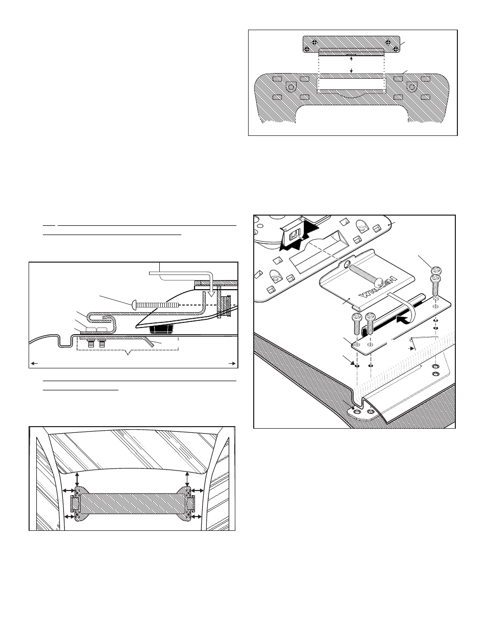
be sure the lightbar is square with the vehicle (Fig. 2).
IMPORTANT! Be very careful not to move the lightbar for
this step. With the lightbar in position, measure 1/4” (or less)
from the end of the mounting foot to the inner edge of the
surface clamp and place the surface clamp onto the vehicle
as shown (Fig. 3). With the surface clamp in its exact
mounting position, (square with the mounting foot) mark the
mounting holes off onto the vehicle roof. Repeat this step for
the opposite side of the lightbar.
3.
Lower the headliner on one side of the vehicle to access the
underside of the roof and make absolutely sure the support
bracket fits into the area.
4.
Remove the lightbar and drill the mounting holes (4 per side).
5.
Apply RTV sealer around the mounting holes, place the
surface clamp onto the roof and insert the 4 machine screws
into the mounting holes (Fig. 4).
6.
Apply RTV sealer to the support bracket where it will come in
contact with the roof. Insert the support bracket between the
headliner and roof (using the handle provided on the support
bracket), line it up with the mounting screws and tighten the
screws securing it to the vehicle (Fig. 4).
7.
Remount the headliner, repeat steps 4 and 5 for the other
side of the vehicle and remount that side of the headliner.
8.
With the headliner remounted, place the lightbar onto the
vehicle and secure the mounting straps to the surface clamps
you installed then firmly tighten all hardware (Fig. 4).
IMPORTANT! It is the responsibility of the installation
technician to make sure that the installation and operation of
this product will not interfere with or compromise the
operation or efficiency of any vehicle equipment! Before
returning the vehicle to active service, visually confirm the
proper operation of this product, as well as all vehicle
components/equipment.
Fig. 1
5/16 - 18 X 1-3/4 Phillips
Round HD. Metal Screw
Foot
Pad
Mounting Strap
Machine Screw
Surface Clamp
Rain
Gutter
Flat Area of Roof Surface
Door
Center of Vehicle
Support Bracket
NOTE: With the strap in place on the vehicle
roof, there should be 3/8" distance (max)
between the end of the strap and the cage
nut (before tightening).