Whelen 0SU0EDCR User Manual
Automotive: lightheads, Engineering company inc
Page 1
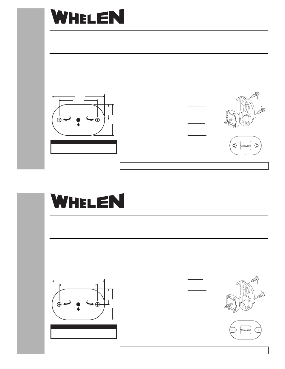
.915"
.457"
1.550"
1.130"
Mounting Hole for
heet etal crew
#6 S
M
S
3/8” WIRE
HOLE
CAUTION! DO NOT LOOK DIRECTLY AT THESE LEDS
WHILE THEY ARE ON. MOMENTARY BLINDNESS AND/OR
EYE DAMAGE COULD RESULT!
IMPORTANT WARNING!
51 Winthrop Road,
Chester, Connecticut 06412-0684
Phone: (860) 526-9504
Fax: (860) 526-4078
FLASHER
Colored Wire:
Grey Wire:
+24VDC
Ground
STEADY
Colored Wire:
Grey Wire:
+24VDC
Ground
Specifications
Input Voltage:
Input Current:
25.6 VDC
11mA (TYP)
Specifications
25.6 VDC
35 mA (TYP)
22mA (TYP)
150 FPM
Input Voltage:
Input Current
PEAK:
Average:
Flash Rate:
#6 X 3/8
PPHSMS
FLANGE
CORRECT ORIENTATION
®2008 Whelen Engineering Company Inc.
Form No. 14239A (071009)
Automotive:
Lightheads
Installation Guide:
LED Clearance/Warning Light (24V)
®
ENGINEERING COMPANY INC.
Internet: www.whelen.com
Sales e-mail: [email protected]
Canadian Sales e-mail: [email protected]
Customer Service e-mail: [email protected]
For warranty information regarding this product, visit www.whelen.com/warranty
WARNING! All customer supplied wires that connect to the positive terminal of the battery must be sized to supply at least 125% of the
maximum operating current and FUSED at the battery to carry the load. DO NOT USE CIRCUIT BREAKERS WITH THIS PRODUCT!
Permanent mounting of this product will require drilling. It is absolutely necessary to make sure that no other vehicle components could be
damaged by this process. Check both sides of the mounting surface before starting. If damage is likely, select a different mounting location.
1. Place the flange onto the mounting surface and mark off the location for the two mounting screws. Also mark off the wire access hole location
between the two screw holes. NOTE: There is an optional wire exit hole on the bottom of the flange if you prefer the wires to exit the bottom of the
lighthead. Be sure the installation will not interfere with anything behind the mounting surface.
2. Drill two pilot holes for the two #6 x 3/8"
sheet metal mounting screws and a 3/8”
wire access hole. Be sure to thoroughly
deburr this hole.
3. Feed the wires through the gasket and
wire access hole and mount the lighthead
with supplied mounting screws. NOTE:
Make sure Whelen logo on lens is
oriented correctly after mounting.
4. Extend the wires to your power source
and fuse the positive wire @ 1 Amp then
test the lighthead.
IMPORTANT! Before returning this
vehicle to active service, visually
confirm proper operation of this product,
as well as all vehicle components/
equipment.