Whelen M9A24 User Manual
Important warning
©2009 Whelen Engineering Company Inc.
Form No. 14272G (013013)
Safety First: This document provides all the necessary information to allow your Whelen product to be properly and safely installed. Before beginning the installation
and/or operation of your new product, the installation technician and operator must read this manual completely. Important information is contained herein that could
prevent serious injury or damage.
®
ENGINEERING COMPANY INC.
51 Winthrop Road
Chester, Connecticut 06412-0684
Phone: (860) 526-9504
Fax: (860) 526-4078
Sales Email:[email protected]
Canadian Sales:[email protected]
Customer Service:[email protected]
www.
.com
M9 Series LED Lighthead (2- & 5-wire) (24-Volt)
For warranty information regarding this product, visit
www.whelen.com/warranty
External flasher models draw less current than a normal automotive bulb. If your
flasher does not operate properly, use a Whelen® flasher.
1.
2.
3.
NOTE: On the back of the gasket, the word "BOTTOM" shows
the correct orientation.
4.
5.
RED - Flash Mode
VIOLET - Low Power:
Latching Mode:
(A toggle switch is preferred)
WHITE/VIO - ScanLock™ Pattern Selection:
TO CYCLE THROUGH ALL PATTERNS:
TO SET A PATTERN AS DEFAULT:
TO RESET TO THE FACTORY DEFAULT PATTERN:
GREY - SYNC:
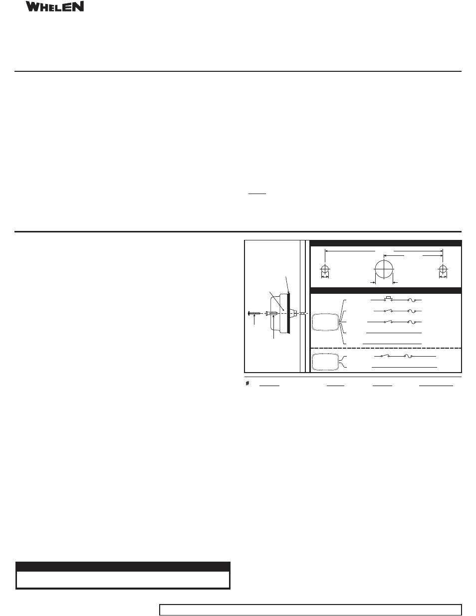
Using the information shown below, mark 2 mounting holes and a wire access hole
location onto the mounting surface.
Drill two 1/4" diameter mounting holes and a 5/8" (minimum) wire access hole in the
mounting surface.
Install the round hole screw grommets (supplied) into these mounting holes. Select the
gasket appropriate for your installation. Use the formed gasket when mounting to a
smooth, flat surface.
Use the adhesive-backed gasket for all other installations.
Adhere the gasket onto the lighthead so that it is centered and completely flat against the
rear surface of the lighthead.
Using appropriately sized wires (minimum 18 AWG), extend the lighthead wires to their
connections. Refer to the illustration for wiring and fusing information.
Position the lighthead onto the mounting surface and secure to the vehicle using the two
supplied #8 sheet metal screws.
:
Apply +VBAT to the RED wire to activate the lighthead in “flash mode”. In flash mode, you
may change the flash pattern using Scan-Lock™.
The type of switch used depends on how the operator wishes Low Power to function.
By applying +VBAT to the VIO wire for less than 1 sec., the lighthead is
“latched” into low power. The unit must be turned off and then back on to restore normal
operation.
Applying +VBAT to the VIO wire for more than 1 sec. holds the lighthead in
low power mode until voltage is removed.
This feature allows the user to select from
several available flash patterns. Lighthead must be switched on for Scan-Lock to work.
Apply +VBAT to the WHT/ VIO wire for less than 1
second and release. To cycle backward through patterns apply +VBAT to the WHT/VIO wire
for over 1 second and release.
Allow the pattern to run for more than 5 seconds. The
lighthead will now display this pattern when active.
Turn off power. While applying +VBAT
to the WHT/VIO wire, turn power on. The lighthead will reset to its default pattern.
To SYNC 2 lightheads, configure both lightheads to display the same Phase 1
(Simultaneous) pattern. Turn power off and connect the GREY wire from each lighthead
together. Activate the lightheads and their patterns will be synchronized. To configure 2
lightheads to alternate their patterns, advance either lighthead to Phase 2 (Alternating) of the
current pattern.
(A momentary switch is preferred)
Level Mode:
LED Color
3A Fuse*
*5A for Scenelight
To +VBAT
To Ground
SP/ST
BLK/WHT
MOUNTING DIMENSIONS
9.062"
4.531"
0.25"
0.625"
0.25"
WIRING DIAGRAM
Pattern
SYNC?
CA Title XIII?
Phase
1
SignalAlert™CAL
PH.1
YES
YES
2
SignalAlert™ CAL
PH.2
YES
YES
3
CometFlash® 75
PH.1
YES
NO
4
CometFlash® 75
PH.2
YES
NO
5
DoubleFlash 75
PH.1
YES
YES
6
DoubleFlash 75
PH.2
YES
YES
7
SingleFlash 75
PH.1
YES
YES
8
SingleFlash 75
PH.2
YES
YES
9
ComAlert™ 75
PH.1
YES
NO
10
ComAlert™ 75
PH.2
YES
NO
11
LongBurst™ 75
PH.1
YES
NO
12
LongBurst™ 75
PH.2
YES
NO
13
SingleFlash 60
PH.1
NO
YES
14
SingleFlash 90
PH.1
NO
YES
15
SingleFlash 120
PH.1
NO
YES
16
SingleFlash 300
PH.1
NO
NO
17
DoubleFlash 150
PH.1
NO
NO
18
ComAlert™ 150
PH.1
NO
NO
19
ActionFlash™50
PH.1
NO
NO
20
ActionFlash 150
PH.1
NO
NO
21
ModuFlash™
PH.1
NO
NO
22
DoubleFlash 120
PH.1
NO
YES
23
TripleFlash™75
PH.1
NO
YES
24
TripleFlash 120
PH.1
NO
YES
25
Action SF 60/120
PH.1
NO
YES
26
Action SF120/TF75
PH.1
NO
YES
27
CalScan™
PH.1
NO
YES
28
ActionScan™
PH.1
NO
NO
29 SignalAlert™ Steady
PH.1
NO
NO
30 Steady
PH.1
NO
YES
*
*
*Low power not available for this pattern.
M
O
U
N
T
I
N
G
S
U
R
F
A
C
E
#8 x 1"
PPHSMS
M9 Assembly
Slotted Hole
Screw Grommet
!
!
!
!
!
!
Proper installation of this product requires the installer to have a good understanding of
automotive electronics, systems and procedures.
Failure to use specified installation parts and/or hardware will void the product warranty!
If mounting this product requires drilling holes, the installer MUST be sure that no vehicle
components or other vital parts could be damaged by the drilling process. Check both
sides of the mounting surface before drilling begins. Also de-burr any holes and remove
any metal shards or remnants. Install grommets into all wire passage holes.
Do not install this product or route any wires in the deployment area of your air bag.
Equipment mounted or located in the air bag deployment area will damage or reduce the
effectiveness of the air bag, or become a projectile that could cause serious personal
injury or death. Refer to your vehicle owner's manual for the air bag deployment area. The
User/Installer assumes full responsibility to determine proper mounting location, based
on providing ultimate safety to all passengers inside the vehicle.
For this product to operate at optimum efficiency, a good electrical connection to chassis
ground must be made. The recommended procedure requires the product ground wire to
be connected directly to the NEGATIVE (-) battery post.
Do not attempt to activate or control this device in a hazardous driving situation.
!
!
!
!
!
If this product uses a remote device to activate or control this product, make sure that this
control is located in an area that allows both the vehicle and the control to be operated
safely in any driving condition.
This product contains either strobe light(s), halogen light(s), high-intensity LEDs or a
combination of these lights. Do not stare directly into these lights. Momentary blindness
and/or eye damage could result.
Use only soap and water to clean the outer lens. Use of other chemicals could result in
premature lens cracking (crazing) and discoloration. Lenses in this condition have
significantly reduced effectiveness and should be replaced immediately. Inspect and
operate this product regularly to confirm its proper operation and mounting condition. Do
not use a pressure washer to clean this product.
FAILURE TO FOLLOW THESE PRECAUTIONS AND INSTRUCTIONS COULD RESULT IN
DAMAGE TO THE PRODUCT OR VEHICLE AND/OR SERIOUS INJURY TO YOU AND YOUR
PASSENGERS!
WARNING! All customer supplied wires that connect to the positive (+) terminal of the
battery must be sized to supply at least 125% of the maximum operating current and
“at the battery” to carry that load. DO NOT USE CIRCUIT BREAKERS WITH THIS
PRODUCT!
FUSED
Gasket Note -
Use the
gasket
on flat, smooth surfaces
. For diamond plate,
use optional gasket,
P/N 38-016B624-01
included
only
To +VBAT
To +VBAT
To +VBAT
To Ground
WHT/VIO
LED Color
VIOLET
BLACK
GREY
SYNC
1A Fuse
1A Fuse
3A Fuse
SP/ST
SP/ST
MOM. SW
M9
Lighthead
(5-Wire)
M9
Lighthead
(2-Wire)
CAUTION! DO NOT LOOK DIRECTLY AT THESE LEDS WHILE THEY ARE ON.
MOMENTARY BLINDNESS AND/OR EYE DAMAGE COULD RESULT!
IMPORTANT WARNING!