Amprobe ACD-30P Clamp-On-Power-Meters User Manual
Page 19
18
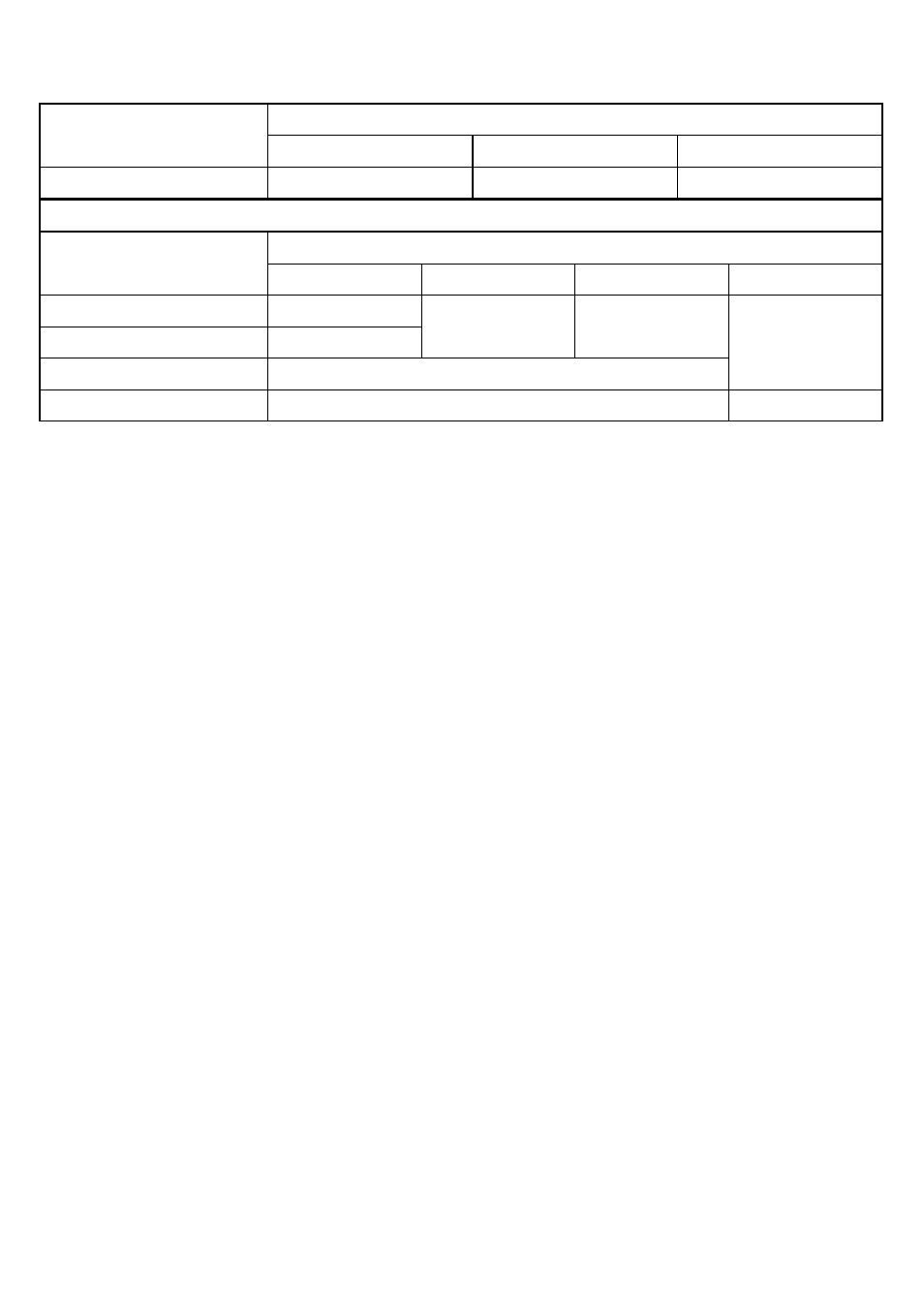
Power
Accuracy
1) 2)
RANGE
0 ~ 600.0kVA
F ~ 10th
11th ~ 46th
47th ~ 51st
@ PF = 0.99 ~ 0.1
2.0%+6d 3.5%+6d 5.5%+6d
Accuracy
1) 3)
RANGE
0 ~ 600.0kW / kVAR
F ~ 10th
11th ~ 25th
26th ~ 46th
47th ~ 51st
@ PF = 0.99 ~ 0.70
2.0%+6d
@ PF = 0.70 ~ 0.50
3.0%+6d
3.5%+6d 4.5%+6d
@ PF = 0.50 ~ 0.30
4.5%+6d
10%+6d
@ PF = 0.30 ~ 0.20
10%+6d 15%+6d
1)
Specified accuracy is for ACA clamp measurement at the center of jaws. When the
conductor is not positioned at the jaw center, position errors introduced are:
Add 1% to specified accuracy for ACA measurements made WITHIN jaw marking
lines (away from jaw opening)
Accuracy is not specified for ACA measurement made BEYOND jaw marking lines
(toward jaws opening)
2)
Add 1% to specified accuracy @ ACA fundamental < 5A or ACV fundamental < 90V.
Accuracy is not specified @ ACA fundamental < 1A or ACV fundamental < 30V
3)
Add 1% to specified accuracy @ ACA fundamental < 5A or ACV fundamental < 90V.
Accuracy is not specified @ ACA fundamental < 2A or ACV fundamental < 50V
A-lags
1)
Indication:
“A-lags” LCD annunciator turns on to indicate an inductive circuit, or Current A lags
Voltage V (i.e., phase-shift angleθ is “+”).
1)
A-lags Indication is specified at 50/60Hz fundamental without harmonics, and at ACV >
90V, ACA > 9A, & PF < 0.95