Amprobe ACD-30P Clamp-On-Power-Meters User Manual
Page 9
8
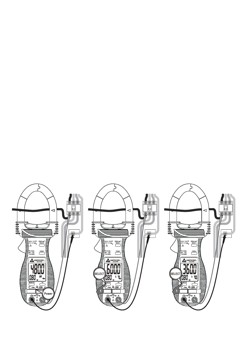
●PF (Total Power Factor) displays simultaneously in the secondary mini display.
Denoting efficiency, absolute PF value is adopted.
●“A-lags” LCD annunciator turns on to indicate an inductive circuit, or Current A lags
Voltage V (i.e., phase-shift angle θ is “+”).
On the contrary, together with significant PF values, WITHOUT “A-lags” turn on to
indicate a capacitive circuit, or Current A leads Voltage V (i.e., phase-shift angle θ is
“-”).
Note:
1. When measuring load circuits with power absorptions as in most applications, positive
W (Real Power) readings indicate correct measurement setups. Negative readings (LCD
annunciator “-“ turns on) indicate either the clamp-on jaws direction or the test leads
polarity is reversed in such cases. Correct the setups to get proper “A-lags” indications.
2. When encountering largely distorted waveforms, “A-lags” detection might be affected
due to the influence of harmonics. As mentioned, it is recommended to deal with (e.g.
filter out) harmonics before correcting phase-shift problems.
●Measuring One or Single Phase Power Parameters: