Appendix a, A.1 device’s rj-45 pin assignments, A.2 rj-45 cable pin assignment – PLANET GT-1205A User Manual
Page 12
12
4. Appendix A
A.1 Device’s RJ-45 Pin Assignments
1000Mbps, 1000Base T
RJ-45 Connector pin assignment
Contact
MDI
MDI-X
Contact
MDI
MDI-X
1
BI_DA+
BI_DB+
5
BI_DC-
BI_DD-
2
BI_DA-
BI_DB-
6
BI_DB-
BI_DA-
3
BI_DB+
BI_DA+
7
BI_DD+
BI_DC+
4
BI_DC+
BI_DD+
8
BI_DD-
BI_DC-
10/100Mbps, 10/100Base-TX
RJ-45 Connector pin assignment
Contact
MDI Media Dependant
Interface
MDI-X Media Dependant
Interface-Cross
1
Tx + (transmit)
Rx + (receive)
2
Tx - (transmit)
Rx - (receive)
3
Rx + (receive)
Tx + (transmit)
4, 5
Not used
6
Rx - (receive)
Tx - (transmit)
7, 8
Not used
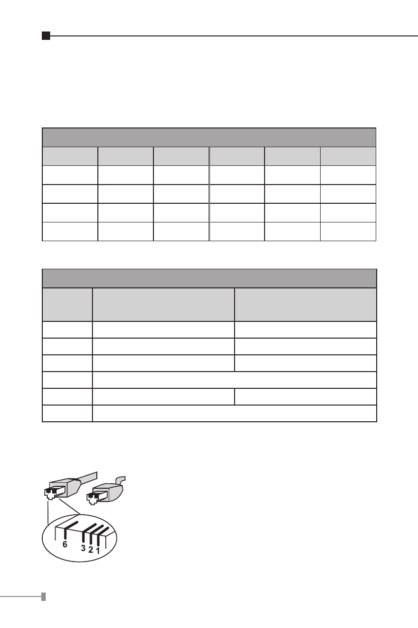
A.2 RJ-45 Cable Pin Assignment
The standard RJ-45 receptacle/connector
There are 8 wires on a standard UTP/STP
cable and each wire is color-coded. The
following shows the pin allocation and color of
straight cable and crossover cable connection: