A.3 fiber optical cable connection parameter – PLANET GT-1205A User Manual
Page 13
13
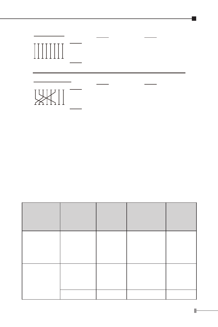
Straight Cable
Cross Over Cable
SIDE 1
SIDE 1
SIDE 2
SIDE 1
SIDE 2
1 2 3 4 5 6 7 8
1 2 3 4 5 6 7 8
1 2 3 4 5 6 7 8
1 2 3 4 5 6 7 8
SIDE 2
1 = White/Orange
2 = Orange
3 = White/Green
4 = Blue
5 = White/Blue
6 = Green
7 = White/Brown
8 = Brown
1 = White/Orange
2 = Orange
3 = White/Green
4 = Blue
5 = White/Blue
6 = Green
7 = White/Brown
8 = Brown
SIDE 1
SIDE 2
1 = White/Orange
2 = Orange
3 = White/Green
4 = Blue
5 = White/Blue
6 = Green
7 = White/Brown
8 = Brown
1 = White/Green
2 = Green
3 = White/Orange
4 = Blue
5 = White/Blue
6 = Orange
7 = White/Brown
8 = Brown
Figure A-1: Straight-Through and Crossover Cable
Please make sure your connected cables are with same pin
assignment and color as above picture before deploying the
cables into your network.
A.3 Fiber Optical Cable Connection Parameter
The wiring details are as below:
Fiber Optical patch Cables:
Standard
Fiber
Diameter
(micron)
Modal
Bandwidth
(MHz * km)
Max.
Distance
(meters)
1000Base-SX Multi-mode
62.5
62.5
50
50
100
200
400
500
220
275
500
550
1000Base-LX
Multi-mode
62.5
50
50
5
4
5
550
Single-mode 9
N/A
5000*