Hardware description, 1 front panel, 1 ports connection – PLANET VF-102-KIT User Manual
Page 10: 2 led indicators
10
2. HARDWARE DESCRIPTION
2.1 Front Panel
The units’ front panel provides a simple interface monitoring the
converter. There are FC fiber optical interface and VIDEO socket
in the front panel. For the VF-102-T / VF-102-R which reverse
data connector, the RS485/422 DATA port may be connected to
the user’s interface end.
PWR
GND
LNK
VF-102
Video over Fiber Converter
OPTIC
VIDEO
RS422/485
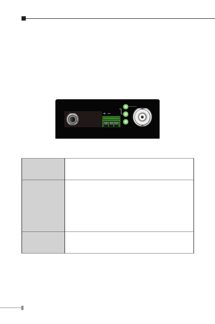
2.1.1 Ports connection
Video
Connection:
Connecting the video signal to or from the
product through a 75Ω coax cable with BNC
plug.
Async-data
Connection:
● Connect the output data port (eg. TX+ and
TX-) of other control device to the RX+ and
RX- of the RX.
● Connect the input data port (eg. RX+ and
RX-) of other under controlled device to the
TX+ and TX- of the TX.
● GND in both TX and RX should be
connected directly to user’s equipment.
Fiber
Connection:
Connect the fiber-optic cable pigtail (with
FC/PC or ST/PC optical connector) to the
product’s FIBER port.
2.1.2 LED Indicators
The rich diagnostic LEDs on the front panel can provide the
operating status of individual port and whole system. There are
“POWER”, “VIDEO”, “LINK” 3 LEDs in the front panel of TX/RX.
Each LED lightens means: