PLANET IAP-2000PE User Manual
Package contents, Hardware installation, Requirements
- 5 -
- 1 -
- 2 -
- 3 -
- 4 -
- 6 -
- 7 -
- 8 -
1. Package Contents
Thank you for choosing PLANET Industrial Wireless
Access Point.
The PLANET Industrial Wireless Access Point comes with
one of the following models.
● IAP-2000PS: 2T2R 802.11b/g/n 4-Port 10/100Mbps
with 4-Port PoE (PSE) Industrial
Wireless Access Point (RJ-45, 100m)
● IAP-2000PE: 2T2R 802.11b/g/n 4-Port 10/100Mbps
with 1-Port PoE (PD) Industrial
Wireless Access Point (RJ-45, 100m)
● IAP-2001PE: 2T2R 802.11b/g/n 4-Port 10/100Mbps
with 1-Port PoE (PD) + 1-port 100FX
(SFP Slot) Industrial Wireless Access
Point
Open the box of the Industrial Wireless Access Point
and carefully unpack it. The box should contain the
following items:
The IAP-200x series Industrial Wireless Access Point x 1
User’s Manual CD x 1
Quick Installation Guide x 1
DIN Rail Kit x 1
Wall Mount Kit x 1
5dBi Antenna x 2
If there is any item missing or damaged, please contact
your local reseller for replacement.
3. Hardware Installation
3.1 Front Panel
Figure 3-1 & 3-2 & 3-3 show the front panels of
Industrial Wireless Access Points.
1
(PoE)
WPS
5
100Base-FX
Reset
2
3
4
P1
P2 PWR FAL
Ant1
Ant2
FX WPS WLAN
1
PoE
2
3
4
SEC
802.11n Industrial Access Point
IA
P-2
00
1P
E
Figure 3-1
IAP-2000PS
Figure 3-2
IAP-2000PE
Figure 3-3
IAP-2001PE
V1 - V1 + V2 - V2 +
Figure 3-5 The Top Panel of IAP-2000PE / IAP-2001PE
10/100Base-TX Ports / 100Base-FX Port
LED
Color
Function
1 ~ 4
Green
It indicates which RJ-45 port is
link up.
FX
Green
It indicates the Fiber port is
link up.
PoE
Orange
It indicates the device is power
supplied by PoE.
PoE In-Use
Orange
It indicates which RJ-45 port is
providing 48V DV in-line power.
2. Requirements
Workstations of subscribers running Windows 98/
ME, NT4.0, 2000/XP/Vista/7, MAC OS 9 or later,
Linux, UNIX or other platform compatible with TCP/IP
protocols.
The Workstation installed with Ethernet NIC (Network
Card).
Ethernet Port connection
Network cables - Standard network (UTP) cables
with RJ-45 connectors.
The Above PC is installed with WEB Browser and
JAVA runtime environment Plug-in.
Note
It is recommended to use Internet Explore
7.0 or above to access IAP-200x Series.
3.2 LED Indicators
System
LED
Color
Function
P1
Green
It indicates the power 1 has power.
P2
Green
It indicates the power 2 has power.
PWR
Green
It indicates the machine is power on.
FAL
Green
It indicates either the power 1 or
power 2 has no power.
Wireless LAN
LED
Color
Function
WPS
Orange It indicates WPS is enabled.
WLAN
Green
It indicates the wireless LAN is
enabled.
SEC
Orange
It indicates the wireless security
encryption is enabled.
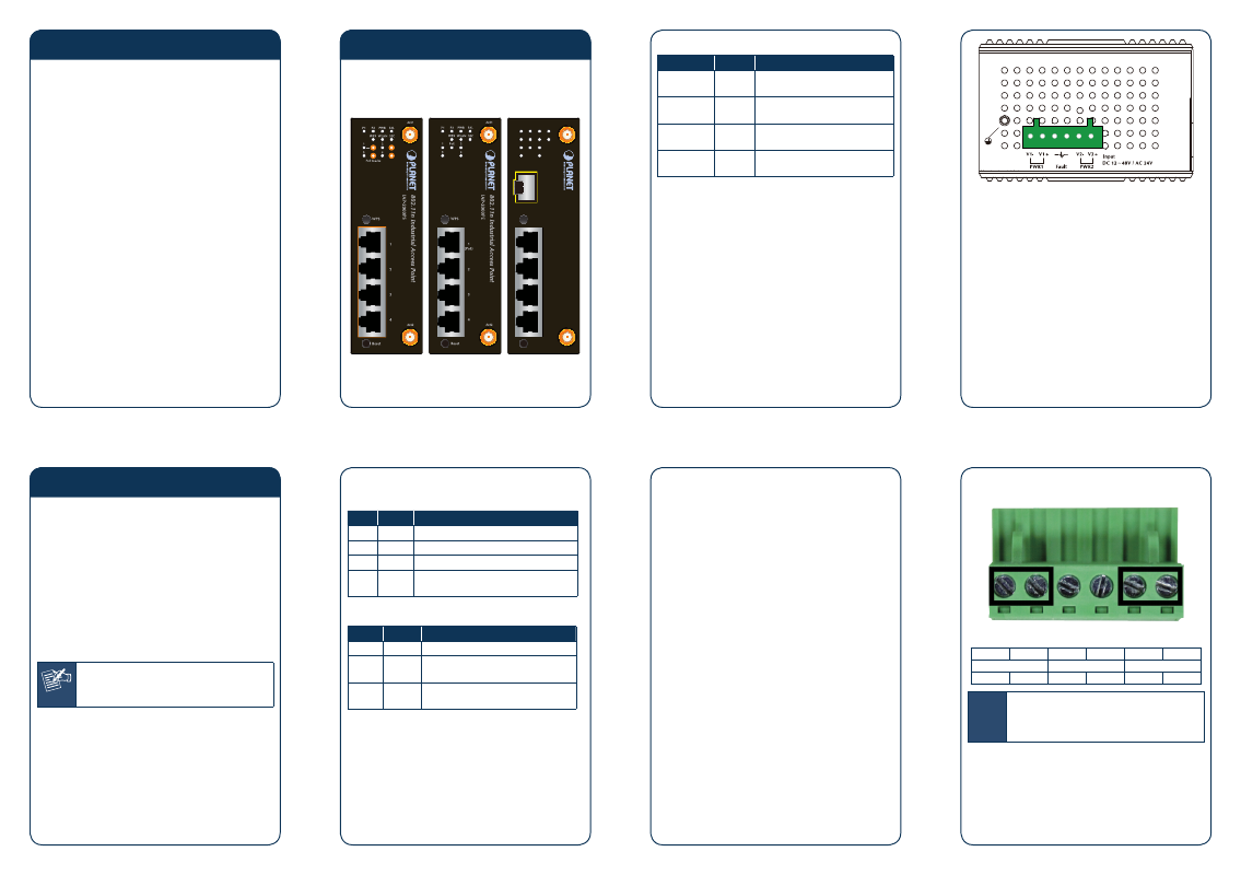
2. Tighten the wire-clamp screws for preventing the
wires from loosing.
Figure 3-6
1
2
3
4
5
6
Power 1
Fault
Power 2
-
+
-
+
Note
The wire gauge for the terminal block should
be in the range between 12 ~ 24 AWG.
Note
The Power input voltage of IAP-2000PS is
DC 24V or 48V only.
The Power input voltage of IAP-2000PE and
IAP-2001PE is DC 12~48V / AC 24V.
3.3 Wiring the Power Inputs
The 6-contact terminal block connector on the top panel
of the Industrial Wireless Access Point is used for two
DC redundant powers input. Please follow the steps
below to insert the power wire.
1. Insert positive / negative DC power wires into the
contacts 1 and 2 for POWER 1, or 5 and 6 for
POWER 2.
V1 - V1 + V2 - V2 +
Figure 3-4 The Top Panel of IAP-2000PS