Erica Synths EDU DIY Mixer Eurorack Module Kit User Manual
Page 39
39
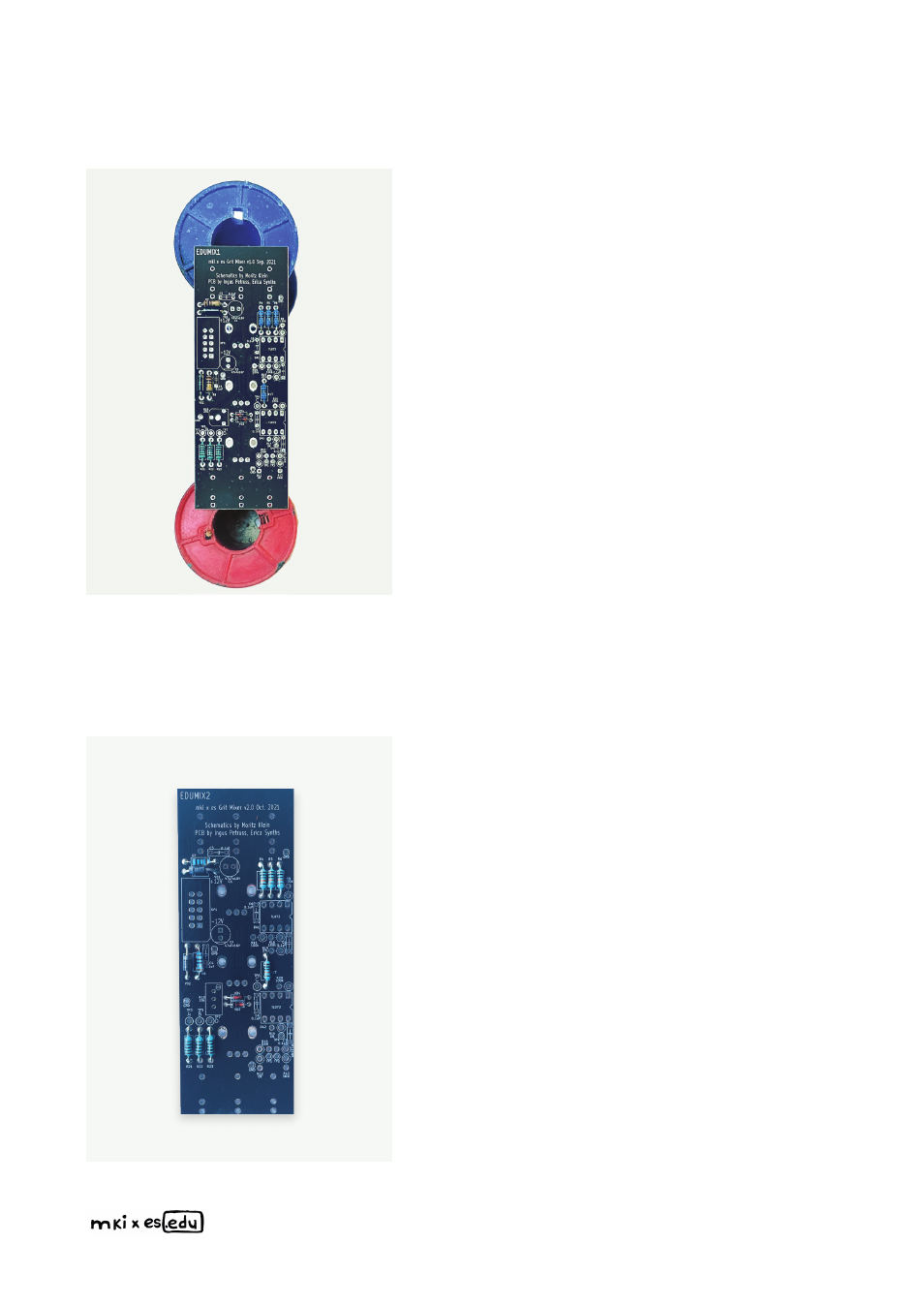
Place the VCF PCB in a PCB holder for
soldering or simply on top of some spacers
(I use two empty solder wire coils here).
I usually start populating PCBs with lower,
horizontally placed components. In this case,
these are some resistors, switching
diodes and the power protection
diodes. Bend the resistor leads and insert
them in the relevant places according to the
part placement diagram above. All compo-
nents on the PCB have both their value and
denomination printed onto the silkscreen. If
you are not sure about a resistor’s value, use
a multimeter to double-check. Next, insert the
diodes. Remember – when inserting the
diodes, orientation is critical! A thick
white stripe on the PCB indicates the cathode
of a diode – match it with the stripe on the
component. Flip the PCB over and solder all
components. Then, use pliers to cut off the
excess leads.