Erica Synths EDU DIY Mixer Eurorack Module Kit User Manual
Page 40
40
Next, insert the first DIP socket, hold it in
place and solder one of the pins. Continue
with the next DIP socket. Make sure the DIP
sockets are oriented correctly – the notch
on the socket should match the notch on the
PCB’s silkscreen. Now, turn the PCB around
and solder all remaining pins of the DIP
sockets. Then proceed with the ceramic
capacitors. Place the PCB in your PCB
holder or on spacers, insert the capacitors
and solder them like you did with the
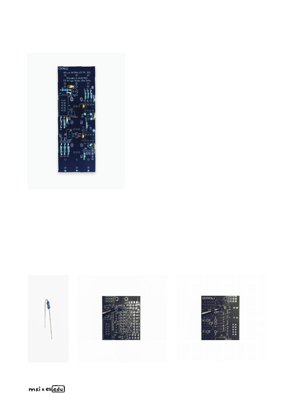
resistors & diodes before. Now your PCB
should look like this:
In order to save space on the PCB, some of our projects, including the VCF, have vertically
placed resistors. The next step is to place & solder those. Bend a resistor’s legs so that its
body is aligned with both legs and insert it in its designated spot. Then solder the longer lead
from the top side of the PCB to secure it in place, turn the PCB around and solder the other
lead from the bottom. You can insert several resistors at once. Once done with soldering, use
pliers to cut off excess leads.