Erica Synths EDU DIY EG Eurorack Module Kit User Manual
Page 12
drive it. And for me, that would get very annoying very fast. But since it’s very easy to
eliminate this kind of external dependency, we’ll get rid of it.
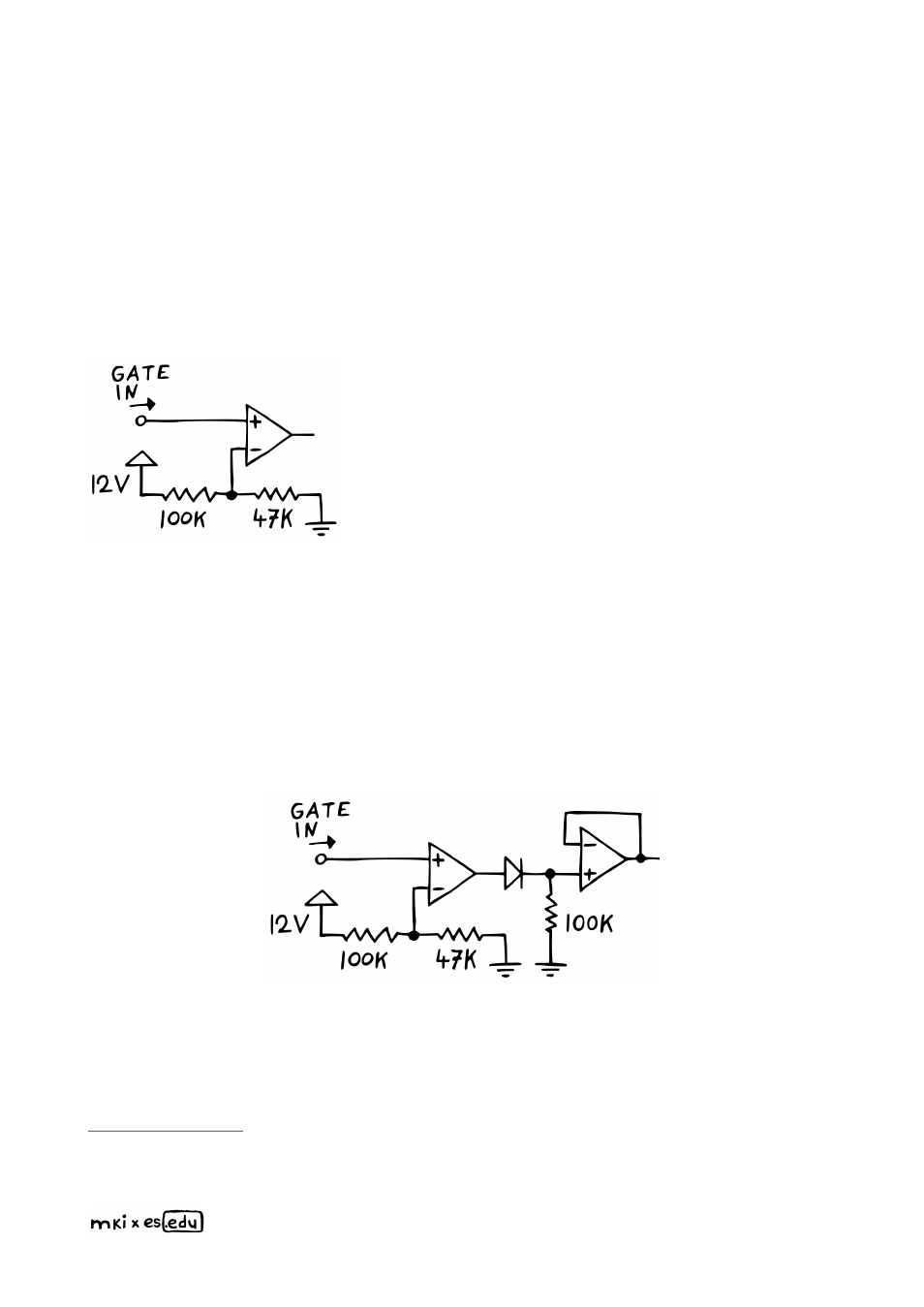
To do that, we use another op amp, which we set up in the comparator configuration.
A
comparator, if you don’t know, basically just looks at an input voltage, compares
that input voltage to a reference voltage, and then tells us which one is higher
. How
does it tells us? By either pushing its output voltage up to the positive
or pulling it down
to the negative supply rail. So in our case, that would be either + or –12 V. Here’s how
this particular setup works in detail.
I’ve set up a voltage divider to get our reference voltage.
A 100k/47k combination gives us approximately 3.8 V to
work with. So whenever our input voltage is higher than
that, the comparator’s output will jump to +12 V. And if
it’s lower, it drops down to –12 V. Why did I choose that
exact threshold? To be honest, mostly just because I
had packs of 100k and 47k resistors lying on my table
when I was testing this. But I still feel that 3.8 V is a
decent value here. It’s low enough so that any
sequencer should be able to trigger the comparator, but
definitely high enough to prevent it from firing randomly
because of electromagnetic interference.
Okay, so now our envelope will always get the same 12 V to work with – as long as our
input signal passes the 3.8 V threshold. But what about the comparator’s low state
output? Once the input drops below the threshold, it will swing down to –12 V.
This is not
ideal, because traditionally, the base line for an envelope’s output is supposed to be
0 V
. Which is why we’ll put a diode, followed by a 100k resistor to ground, between our
comparator’s output and the bu
ff
er’s input.
Here’s what that does. Whenever the comparator is pushing out 12 V, the diode conducts
and we also get about 12 V at the bu
ff
er’s input. But once the voltage turns negative, the
diode will block. Normally, the bu
ff
er’s input would now be undefined (or „floating“). But
since we have a 100k resistor to ground there, that input gets pulled down to 0 V instead.
I keep talking about +/– 12 V as the positive/negative rail voltages because I use a +/– 12 V
power supply myself. You can substitute this with +/– 9 V all throughout the manual if you’re using
batteries.
12