Erica Synths EDU DIY EG Eurorack Module Kit User Manual
Page 8
the two voltages align again. As you can see, this will turn our square wave input into
something like a very basic attack-release envelope.
But before we can try this, we’ll have to think about appropriate values for the capacitor
and resistor. Since we are dealing with a very, very slow square wave oscillation at the
input, they’ll need to be pretty big. Otherwise, the e
ff
ect will be so minimal that we won’t
be able to tell the di
ff
erence.
Also, we’ll probably want to adjust the e
ff
ect’s intensity. For that, we’ve essentially got
two options here: we could change either the capacitor- or resistor value. But since the
former can only be done by hand, and switching components is not the most user-
friendly strategy,
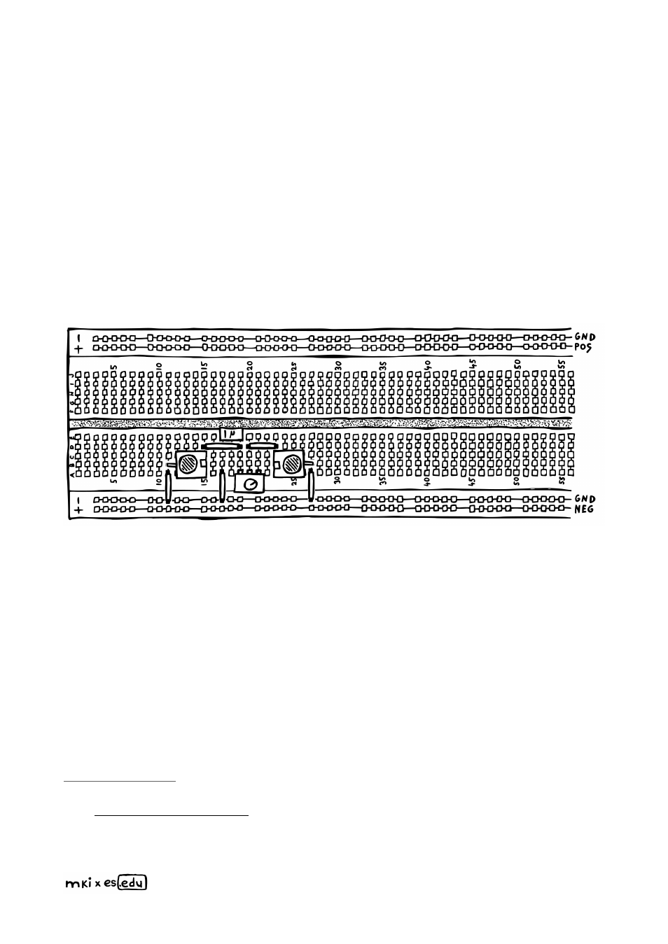
we’re going to replace the fixed resistor with a potentiometer, set
up as a variable resistor
. This way, we can adjust the resistance (and thereby the
steepness of our envelope’s rising and falling edges) on the fly. A 1M pot should give us a
decent enough range here.
To properly test this circuit, you’ll need a square wave LFO and a module with a CV input
like a VCF. Send in the LFO via the right-hand socket, while connecting the other one to
your filter. By turning the potentiometer’s knob, you should be able to dial in a more or
less intense e
ff
ect. Great!
The only problem with this is that the attack- and release
phases are not adjustable independently
. Changing one will always also change the
other.
You can try this chapter’s circuits in a circuit simulator. I’ve already set them up for you right
here: –
you can change all values by double clicking on components.
Read more about potentiometers in the components & concepts appendix (page 30).
A clock module or sequencer with a gate output will also work.
8