DJI O3 Air Unit User Manual
Page 7
©
2022 DJI All Rights Reserved.
5
DJI O3 Air Unit
User Manual
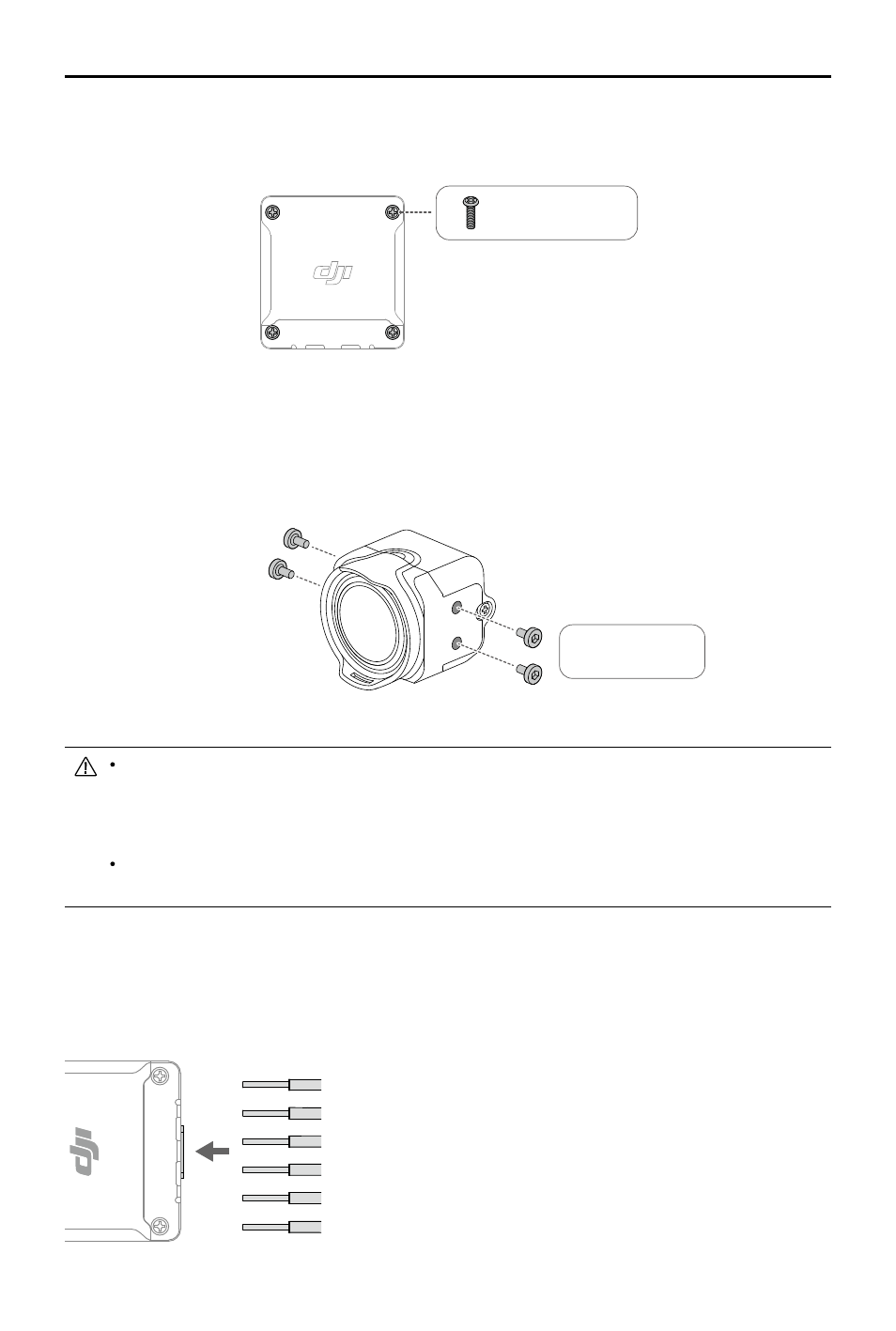
M1.6 x L6 mm
There are four M2 × L4 mm screws attached to both sides of the camera module (the depth of the
screw hole is 2 mm). Remove the screws and use them to mount the camera to the aircraft frame if the
thickness of the aircraft frame is between 2–3 mm. Adjust the camera to an appropriate angle based on
your requirements when installing.
M2 x L4 mm
Choose the screw length carefully when installing the camera module. The length of the screw
should not exceed the sum of the screw hole depth (2 mm) and the thickness of the aircraft
frame. If the screw is too short, the camera module may not be securely fastened. If the screw
is too long, it may cause damage to the internal structure.
To obtain the optimal transmission, keep the antenna away from any metal or carbon fiber
structures, and make sure that the antenna is not blocked by any frame structures.
3-in-1 Cable
Connect the 3-in-1 cable to the 3-in-1 port on the air unit. Refer to the diagram below to solder the other
end of the cable to the flight controller. An electric soldering iron and soldering tin are required for
connection. Make sure that there are no short circuits or open circuits when soldering the cables.
Use glue or screws to install the transmission module. If using screws for installation, remove the four
M1.6 x L6 mm screws on either side of the module. Install the module on a racing drone or other device
with the screws.
RED: Power (7.4-26.4 V)
BLACK: Power GND
WHITE: UART RX (Connects to Flight Controller OSD TX, 0-3.3 V)
GRAY: UART TX (Connects to Flight Controller OSD RX, 0-3.3 V)
BROWN: Signal GND
YELLOW: DJI HDL (Connects to Flight Controller S.Bus, 0-3.3 V)
PIN 2
PIN 1
PIN 4
PIN 3
PIN 6
PIN 5