6 wiring, 1 general wiring guidelines, 1 mechanical connection of the base modules – Pilz PSSu E F 2DOR 8 User Manual
Page 19: Section 6, Wiring, General wiring guidelines, Mechanical connection of the base modules, 6wiring, Din 5264-a
Wiring
Operating Manual PSSu E F 2DOR 8(T)(R)
21334EN07
19
6
Wiring
6.1
General wiring guidelines
Please note:
}
If short circuits occur between the cable from the output to the load and a supply line, it
will no longer be possible to switch off the load. Possible remedies:
–
Use separate multicore cable for supply voltages
–
Use dual actuators, e.g. two contactors in series.
–
Use an additional shutdown device such as a main contactor
}
Use appropriate wiring to exclude short circuits between the outputs!
}
The actuators may be connected using unshielded cables.
}
To prevent contact welding, a fuse should be connected before the output contacts (see
Technical details).
}
With inductive loads, sufficient fuse protection must be provided on all output contacts.
}
When installed at a height of over 2000 m above sea level, only protective extra low
voltage may be connected to the relay contacts.
}
If voltages higher than 50 VAC or 120 VDC are connected to the relay contacts, please
note the following:
–
Specific accident prevention regulations apply.
–
For safety reasons, only the protective earth (PE) may be connected to the Crail of
the supply group.
}
Use copper wiring.
6.1.1
Mechanical connection of the base modules
Procedure:
}
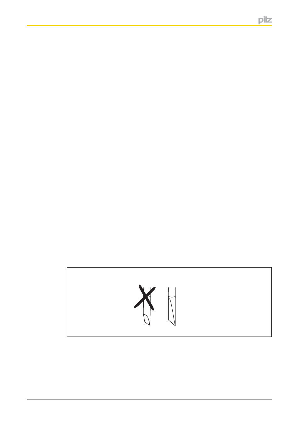
Use a flat blade screwdriver (DIN 5264A)!
DIN 5264-A
}
Strip the wire back 8 mm.
}
If necessary, label the connection level with a colour marker [3].
}
Base module with screw terminals:
–
Use a screwdriver to loosen the screw on the screw terminal [1]
–
Insert the stripped cable into the round fixing hole [2], as far as it will go.