X2y_mount – Altera Device-Specific Power Delivery Network User Manual
Page 18
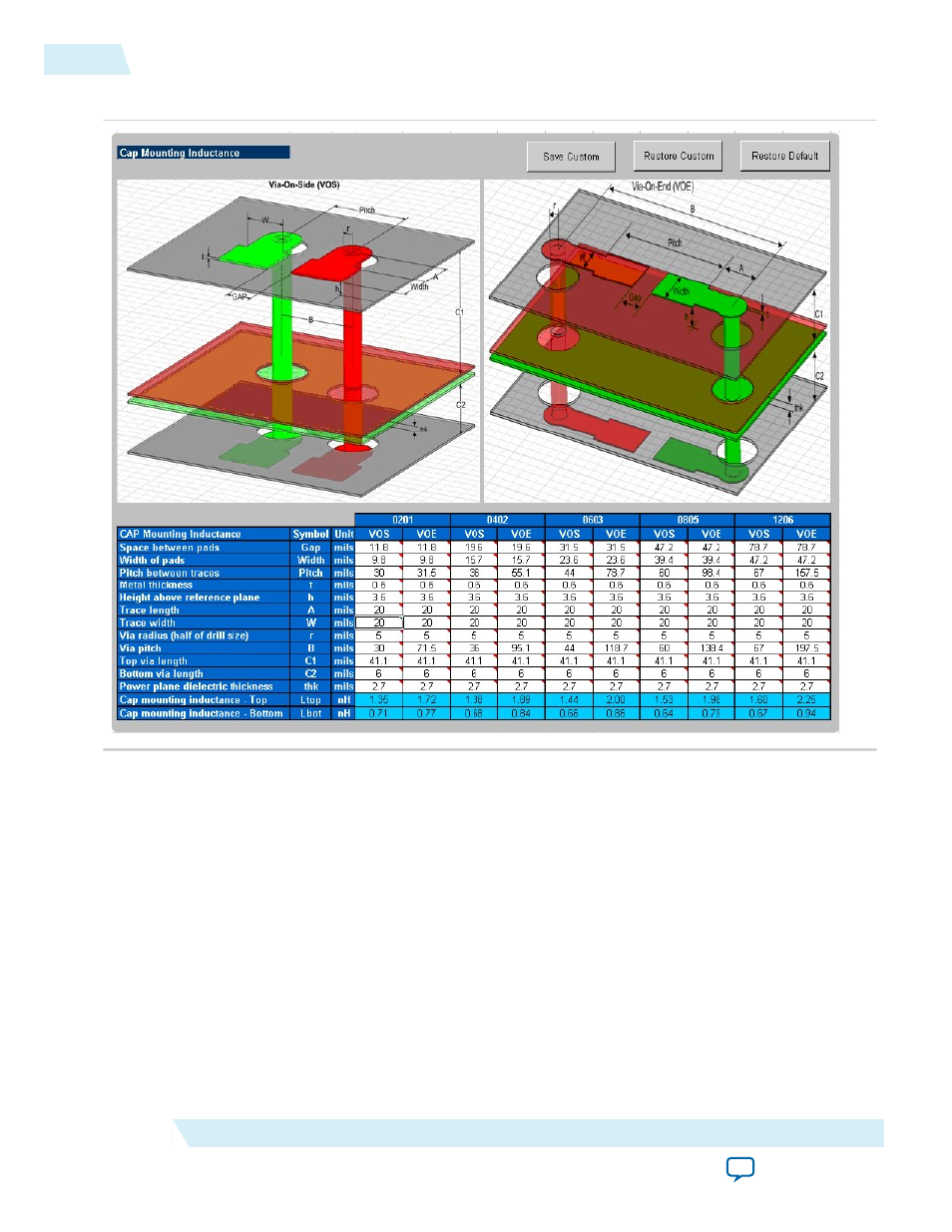
Figure 10: Cap Mount Tab
The capacitor mounting calculation is based on the assumption that the decoupling capacitor is a two-
terminal device. The capacitor mounting calculation is applicable to any two-terminal capacitor with the
following footprints: 0201, 0402, 0603, 0805, and 1206. Enter all the information relevant to your layout,
and the tool provides a mounting inductance for a capacitor mounted on either the top or bottom layer of
the board. Depending on the layout, you can choose between VOE (Via on End) or VOS (Via on Side) to
achieve an accurate capacitor mounting inductance value.
If you plan to use a footprint capacitor other than a regular two-terminal capacitor or X2Y capacitor for
decoupling, you can skip the Cap Mount tab. In this case, you can directly enter the capacitor parasitics
and capacitor mounting inductance in the Library tab (under the Custom field in the Decoupling Cap
section of the library). As with the other tabs, you can save the changes made to the tab, restore the
changes, or restore the tab back to the default settings.
X2Y_Mount
The X2Y Mount tab calculates the capacitor mounting inductance seen by the X2Y decoupling capacitor.
18
X2Y_Mount
UG-01157
2015.03.06
Altera Corporation
Device-Specific Power Delivery Network (PDN) Tool 2.0 User Guide