Pdn decoupling methodology review, Pdn circuit topology, 10 • arria v • arria ii gz • cyclone – Altera Device-Specific Power Delivery Network User Manual
Page 2: V• cyclone iv e • cyclone iv gx • stratix, V• max, And f
The device families supported by the Altera device-specific PDN tool 2.0 are shown at the top of the
Release Notes tab and they include:
• Arria
®
10
• Arria V
• Arria II GZ
• Cyclone
®
V
• Cyclone IV E
• Cyclone IV GX
• Stratix
®
V
• MAX
®
10
PDN Decoupling Methodology Review
The PDN tool 2.0 provides two parameters for guiding PCB decoupling design: Z
TARGET
and F
EFFECTIVE
.
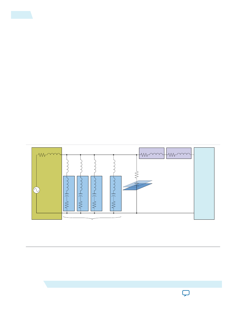
PDN Circuit Topology
The PDN tool 2.0 is based on a lumped equivalent model representation of the power delivery network
topology.
Figure 1: PDN Topology Modeled as Part of the Tool
The PDN impedance profile is the impedance-over-frequency looking from the device side.
Lc1
Cc1
Rc1
Lmnt1
Lc2
Cc2
Rc2
Lmnt2
Lc3
Cc3
Rc3
Lmnt3
Lc N
Cc N
Rc N
Lmnt N
Rp
Cp
Planar
R and C
(4)
Rs
Ls
Rv
Lv
Spreading R and L
(3)
BGA Via R and L
(3)
Rvrm
Lvrm
VRM Model
(1)
Decoupling CAP Model
(2)
Altera
FPGA Device
VRM
Notes:
1. You can define or change VRM parameters in the Library sheet of the PDN tool.
2. You can define or change Decoupling CAPs parameters in the Cap Mount, X2Y Mount, and Library sheets of the PDN tool.
3. Rs and Ls are parasitic capacitances and inductances from BGA balls and PCB traces and connections.
4. Represents PCB layers dedicated to power and ground planes.
2
PDN Decoupling Methodology Review
UG-01157
2015.03.06
Altera Corporation
Device-Specific Power Delivery Network (PDN) Tool 2.0 User Guide