Deriving decoupling in the power-sharing scenarios – Altera Device-Specific Power Delivery Network User Manual
Page 26
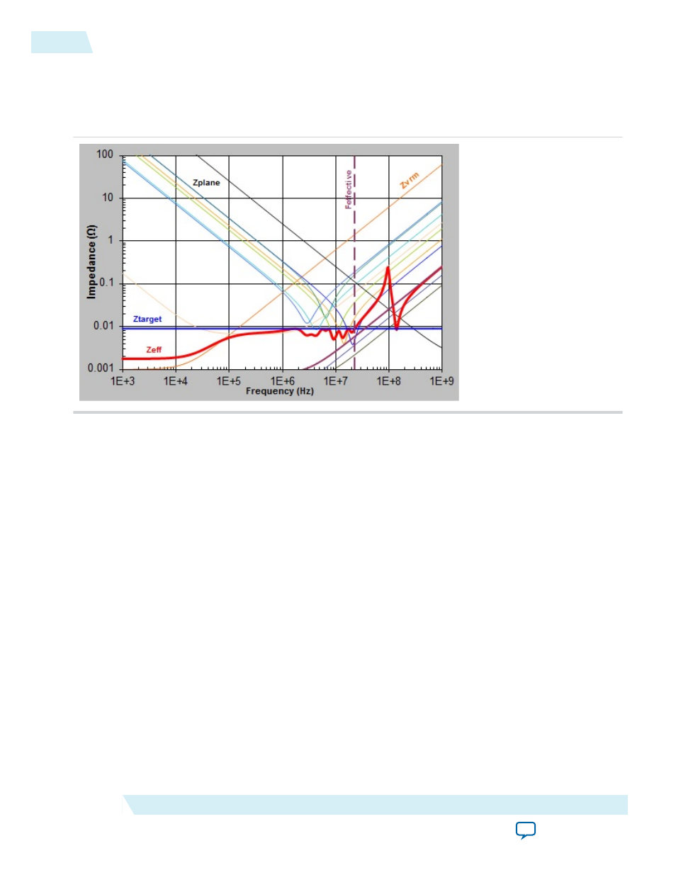
Figure 15: Enlarged Plot of Z
EFF
The design is a decoupling example for a 10AX115R_F40 VCC power rail. Assume that the minimum
voltage supply is 0.9 V, I
MAX
is 10 A, dynamic current change is 50% of I
MAX
, and the maximum allowable
die noise tolerance is 5% of supply voltage. The VCC rail has 50 power BGA vias. The length of BGA via is
assumed to be 60 mil.
The PDN tool 2.0 calculated that Z
TARGET
is 0.0090 Ω and F
EFFECTIVE
is 22.5 MHz. The figure above
shows one of the capacitor combinations that you can select to meet the design goal. As shown in the plot,
Z
EFF
remains under Z
TARGET
up to F
EFFECTIVE
. There are many combinations, but the ideal solution is to
minimize the quantity and the type of capacitors needed to achieve a flat impedance profile below the
Z
TARGET
.
Related Information
on page 27
Deriving Decoupling in the Power-Sharing Scenarios
It is a common practice that several power rails in the FPGA device share the same power supply. For
example, you can connect VCCPT, VCCA_PLL, VCCA_FPLL rails that require the same supply voltage
to the same PCB power plane. This can be required by the design, such as in the memory interface case.
This can also come from the need to reduce bill of materials (BOM) cost. You can use the System_Decap
tab to facilitate the decoupling design for the power sharing scenarios.
When deriving decoupling capacitors for multiple FPGAs sharing the same power plane, each FPGA
should be analyzed separately using the PDN tool 2.0. For each FPGA design, combine the required
power rails as described above and analyze the decoupling scheme as if the FPGA was the only device on
the power rail, taking note of how the current is divided across the devices.
High frequency decoupling capacitors are meant to provide the current needed for AC transitions, and
must be placed in a close proximity to the FPGA power pins. Thus, the PDN tool 2.0 should be used to
derive the required decoupling capacitors for the unique power requirements for each FPGA on the
board.
26
Deriving Decoupling in the Power-Sharing Scenarios
UG-01157
2015.03.06
Altera Corporation
Device-Specific Power Delivery Network (PDN) Tool 2.0 User Guide