Altera PowerPlay Early Power Estimator User Manual
Page 34
3–18
UG-FPGAPWRCAL-2.0
Altera Corporation
PowerPlay Early Power Estimator User Guide: Stratix, Stratix GX & Cyclone FPGAs
October 2005
PowerPlay Early Power Estimator Input Values
the load, and choose the I/O standard used and I/O data rate for each
design module.
describes the values that are entered in the
General I/O Power
section of the PowerPlay early power estimator.
shows an example of the Output Pins report in the Quartus II
software Compilation Report for a design targeting a Stratix device. The
Compilation Report lists the I/O standard used on each pin. In this
example, there are 20 3.3-V LVTTL output pins with 24-mA drive
strength operating at single-data rate with an average load of 10 pF. These
pins are fed by registers that use a 100-MHz clock and toggle an average
of 12.5%.
shows the Stratix PowerPlay early power estimator
and the estimated power consumed by the I/O pins used in this example.
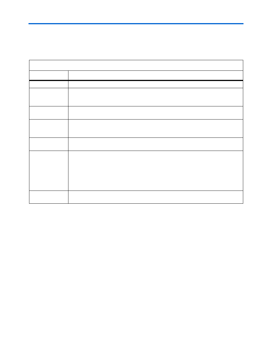
Table 3–8. General I/O Power Section Information
Column Heading
Description
Design Module
Enter a name for the design module in this column. This is an optional value.
f
M A X
(MHz)
Enter the clock frequency for this design module. This is the frequency of the clock used to
feed the I/O registers or the registers that feed the I/O pins. This value is limited by the
maximum I/O pin frequency specification for the device family.
# Outputs &
Bidirectional Pins
Enter the number of output and bidirectional pins used in this design module. A differential
pair of pins should be considered as one pin.
Toggle %
Enter the average percentage of output and bidirectional pins toggling on each clock cycle.
The toggle percentage ranges from 0 to 100%. Typically, the toggle percentage is 12.5%.
To be more conservative, you can use a higher toggle percentage.
Avg. Capacitive
Load (pF)
Enter the average capacitive load in pico-Farads (pF) for the output and bidirectional pins
in this clock domain.
I/O Standard
Select the I/O standard used for the output or bidirectional pins in this clock domain from
the list. The calculated I/O power varies based on the I/O standard. For I/O standards that
recommend termination (for example, SSTL and HSTL), the PowerPlay early power
estimator assumes you are using external termination resistors. If you are not using external
termination resistors, you should choose the LVTTL I/O standard with the same voltage and
similar drive strength as the terminated I/O standard. There are up and down scroll bars to
view all the I/O standards in the drop-down list.
I/O Data Rate
Select the I/O data rate (either single data rate (SDR) or double data rate (DDR)) from the
list.