Altera PowerPlay Early Power Estimator User Manual
Page 36
3–20
UG-FPGAPWRCAL-2.0
Altera Corporation
PowerPlay Early Power Estimator User Guide: Stratix, Stratix GX & Cyclone FPGAs
October 2005
PowerPlay Early Power Estimator Input Values
settings of the programmed V
OD
describes the values that are
entered in the High-Speed Transceiver Blocks section of the PowerPlay
early power estimator.
and
show the GXB Receive Channel and GXB Transmit
Channel reports in the Quartus II software Compilation Report for a
design targeting a Stratix GX device. This example uses a transceiver
block that supports four receive and transmit channels operating at 3.125
Gbps with data output toggling at 25%, a V
OD
of 1,000 mV, and a pre-
emphasis level of 10%.
shows the Stratix GX PowerPlay early
power estimator and the estimated power consumed by the transceiver
blocks used in this example.
1
The High-Speed Transceiver Block section of the PowerPlay
early power estimator includes the receiver and transmitter PLL
power used in the transceiver blocks. You do not need to
estimate the receiver and transmitter PLL power in the PLL
section separately.
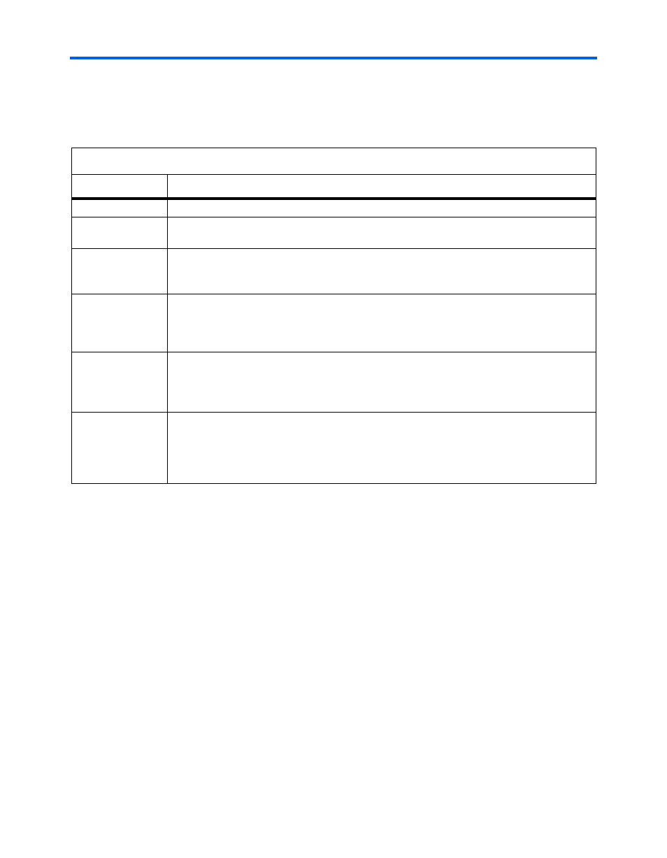
Table 3–9. High-Speed Transceiver Blocks Section Information
Column Heading
Description
Transceiver Block
Enter a name for the transceiver block in this column. This is an optional value.
Data Rate (Gbps)
Enter the maximum data rate (in Gbps) for the receiver and transmitter channels in the
targeted transceiver block. The data rate must be a decimal number from 0 to 3.125 Gbps.
# of Channels
Enter the number of receiver and transmitter channels running at the above data rate. Since
each transceiver block in Stratix GX devices can support up to four high speed transceiver
channels, this value must be an integer value from 0 to 4
Toggle %
Enter the toggle percentage, which is the average percentage of serializer outputs toggling
at each high-speed clock cycle. The toggle percentage ranges from 0 to 100%. Typically,
the toggle percentage is 25%. To be more conservative, you can use a higher toggle
percentage.
V
O D
(mV)
The output differential voltage (V
O D
) of the transmitter channels in mV. The V
O D
values are
selected from a list. The V
OD
values for each Transmitter channel is obtained from the
Quartus II software Compilation Report under Fitter > Resource Section > GXB
Transmitter Channel > Output Buffer Differential Voltage.
Pre-emphasis
Setting (%)
The pre-emphasis percentage levels of the transmitter channels are selected from a list.
The pre-emphasis levels can be set at 0%, 5%, 10%, 15%, 20%, or 25%. The pre-emphasis
setting for each Transmitter channel is obtained from the Quartus II Compilation Report
under Fitter > Resource Section > GXB Transmitter Channel > Output Buffer
Pre-emphasis.