Altera PowerPlay Early Power Estimator User Manual
Page 65
Altera Corporation
3–47
January 2007
PowerPlay Early Power Estimator For Stratix II, Stratix II GX & HardCopy II
Using the PowerPlay Early Power Estimator
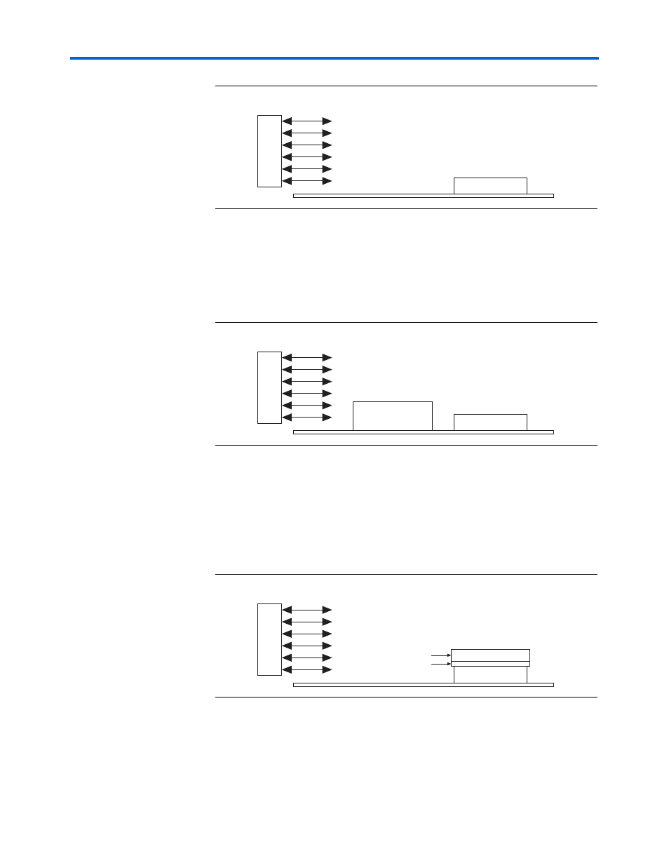
Figure 3–33. Airflow & FPGA Position
In many cases, it is also necessary to take into consideration blocked
airflow. In the example below, there is a device blocking the airflow from
the FPGA significantly reducing the airflow seen at the FPGA. Also, the
airflow from the fan often cools board components and other devices
before reaching the FPGA (
Figure 3–34. Airflow with Component & FPGA Positions
If a custom heat sink is being used, there is no need to enter the airflow
directly into the PowerPlay Early Power Estimator spreadsheet but it is
required to compute the
θ
SA
for the heat sink with the knowledge of what
the airflow is at the device. Most heat sinks have fins located above the
heat sink to facilitate airflow.
shows the case of an FPGA with
a heat sink.
Figure 3–35. AirFlow & Heat Sinks
When placing the heat sink on the FPGA, it is imperative that the
direction of the fins correspond with the direction of the airflow. A top
view shows the correct orientation of the fins (
F
A
N
FPGA
F
A
N
FPGA
Device
F
A
N
FPGA
Heat Sink Fins
Heat Sink