General user interfaces, Led display – Altera Transceiver SI User Manual
Page 30
A–2
Getting Started User Guide
Altera Corporation
Transceiver Signal Integrity Development Kit, Stratix II GX Edition
June 2006
General User Interfaces
General User
Interfaces
This section describes the following general user interfaces, which
provide direct feedback regarding board, clocking, and signal activity:
■
LED display
■
7-segment display
■
DIP switches
■
Push buttons
LED Display
Signals propagating to LEDs indicate board status.
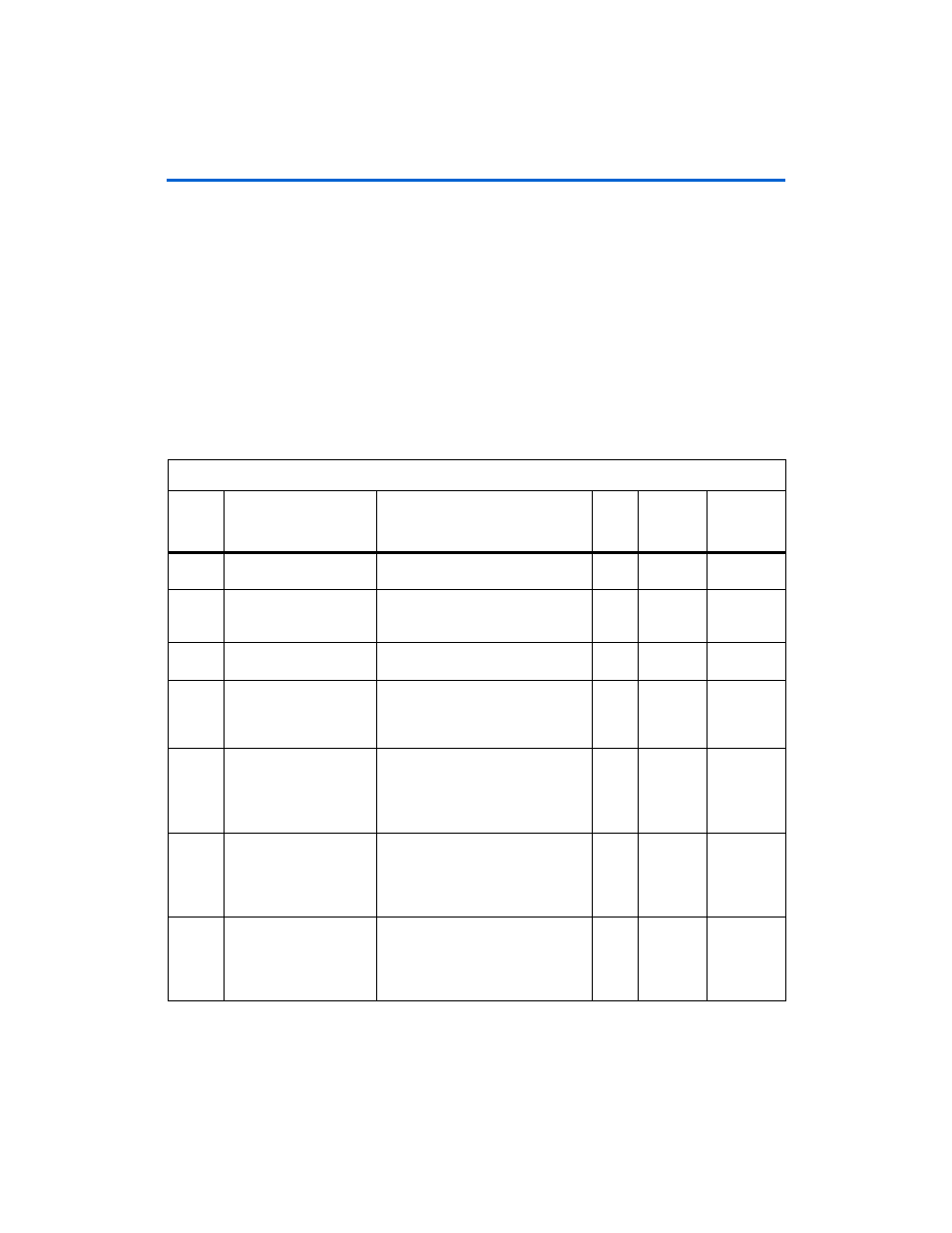
Table A–1
lists the
signal name, description, width, board reference number, and the FPGA
pin in which the signal is connected.
Table A–1. LED Display (Part 1 of 2)
Number
Signal Name
Description
Width
Board
Reference
Number
Connected
to FPGA Pin
Number
1
Tx_pll_locked
Shows whether the TX phase-locked
loop (PLL) is locked to the input clock
1
D1
AE33
2
Rx_syncstatus
W
hen ON, indicates that the receiver
has acquired synchronization with the
input data.
1
D2
AE32
3
Checker_synced
Indicates that the checker is checking
for errors on the received data.
1
D3
AD26
4
Error_flag
The LED is ON for one second when
an error is detected by the pattern
checker. Shows the running error
status.
1
D4
AD25
5
Error
status_first_digit
(1)
The LED is ON if the
LSB[7:0]
of the
error counter reaches
0xFF
. The LED
is reset when
clear_error_counter_switch
is
asserted.
1
D5
AD34
6
Error
status_second_digit
(1)
The LED is ON if the
LSB[15:8]
of
the error counter reaches
0xFF
. The
LED is reset when
clear_error_counter_switch
is
asserted.
1
D6
AE34
7
Error
status_third_digit
(1)
The LED is on if the
LSB[23:16]
of
the error counter reaches
0xFF
. The
LED is reset when
clear_error_counter_switch
is
asserted.
1
D7
AC29