Segment display, Dip switches – Altera Transceiver SI User Manual
Page 31
Altera Corporation
Getting Started User Guide
A–3
June 2006
Transceiver Signal Integrity Development Kit, Stratix II GX Edition
7-Segment Display
The 7-segment displays are used to:
■
Display the VOD, pre-emphasis, DC gain, and equalization values
when reading or writing the PMA settings.
f
Refer to the
“Write and Read PMA values” on page A–6
for more
information.
■
Display the design file name when the system_reset push button
switch is asserted.
■
Display the error count when show_error_count push button
switch is asserted.
1
The VOD values shown by the 7-segment display indicates the
value in mV when multiplied by 100. For example, to show a
VOD of 200mV the 7-segment display shows 02. The display
setting is for a VCCHTX of 1.5 V.
DIP Switches
The DIP switch S7 is used for controlling the different transceiver
parameters.
lists the DIP switch names and describes the
individual switch functions. The DIP switch numbers are shown on the
board’s silkscreen.
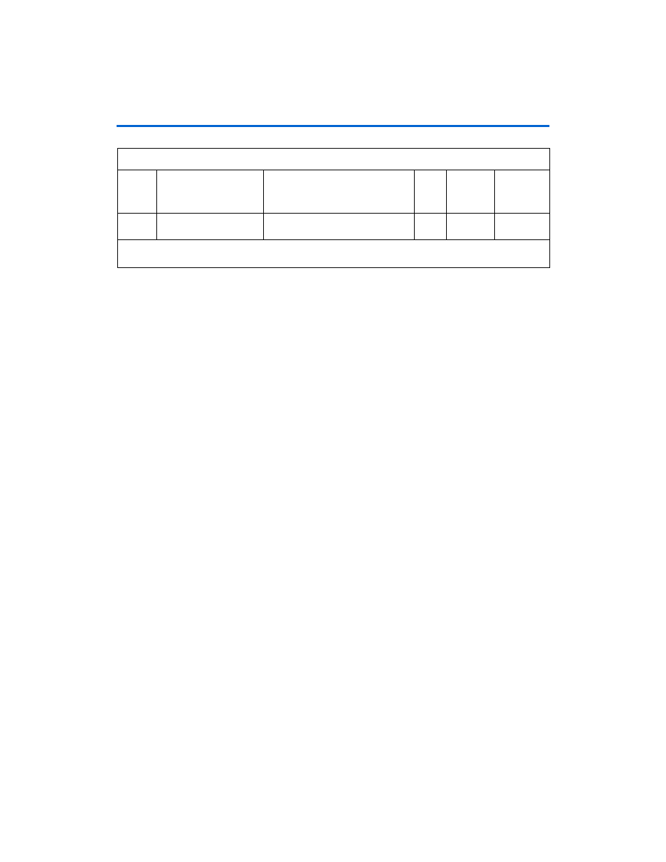
8
Serial_loopback
The LED is ON when serial loopback
is enabled
1
D8
AC28
Note to
Table A–1
:
(1)
The first, second, and third digits display the approximate error count range.
Table A–1. LED Display (Part 2 of 2)
Number
Signal Name
Description
Width
Board
Reference
Number
Connected
to FPGA Pin
Number