Power monitoring, Power monitoring –20 – Altera Transceiver Signal Integrity User Manual
Page 44
6–20
Chapter 6: Board Test System
Power Monitoring
Transceiver Signal Integrity Development Kit,
February 2013
Altera Corporation
Stratix V GT Edition User Guide
Power Monitoring
To measure and view current power information for the development board, you
need to install the free LTpowerPlay™ software, and then connect your PC and the
development board to a Linear Technology DC1613A USB-to-PMBus Controller. Both
the software and the controller interface are available from the Linear Technology
(
ebsite.
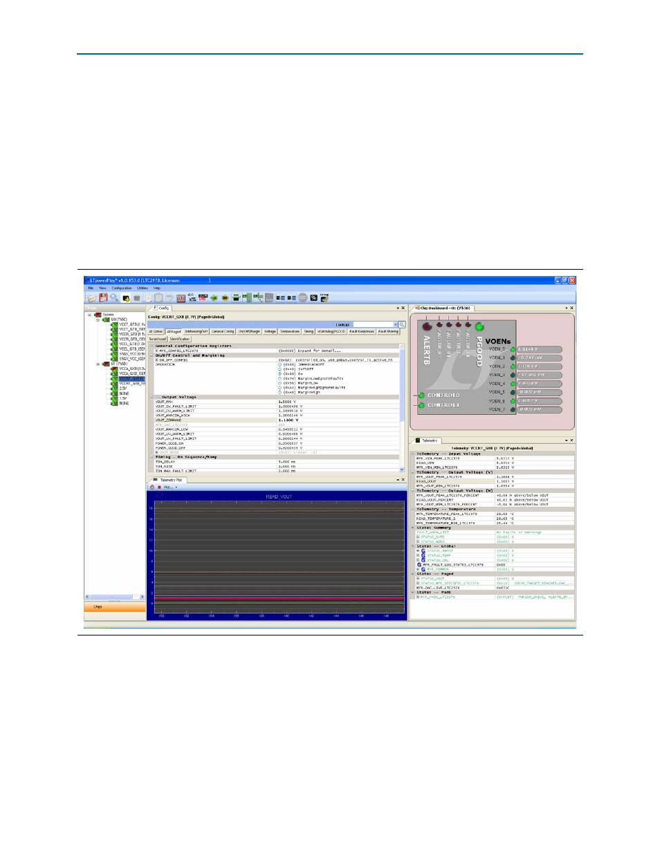
shows the LTpowerPlay GUI.
This application works in conjunction with two LTC2978 Power Monitor/Controller
devices located at U10 and U11 on the board. These two devices are pre-programmed
at the factory to monitor and control specific voltage rails of this board. The
application can be used to monitor, trim, and sequence the specific voltage rails if
necessary. The operator does not need this application otherwise.
1
The DC1613A USB-to-PMBus controller communicates with the LTC
®
2978 on-board
octal PMBus power supply monitor and controller at the U10/11 board reference. For
more information on the LTC2978, refer
The LTC2978 power monitor devices installed on this board are programmed with a
project file that sets up each voltage rail according to a sequence. Each voltage rail
adjusts to its voltage level to within a certain tolerance. These two voltage rails can be
adjusted through switch SW2.
Figure 6–10. LTpowerPlay