Wireless amplifier, A. control panel, B. optional wireless microphone receiver modules – MIPRO ma705(2ce161) User Manual
Page 5
- 3 -
A1
A2
A3
A4
A5
A6
A7
A8
A9
Operating Manual
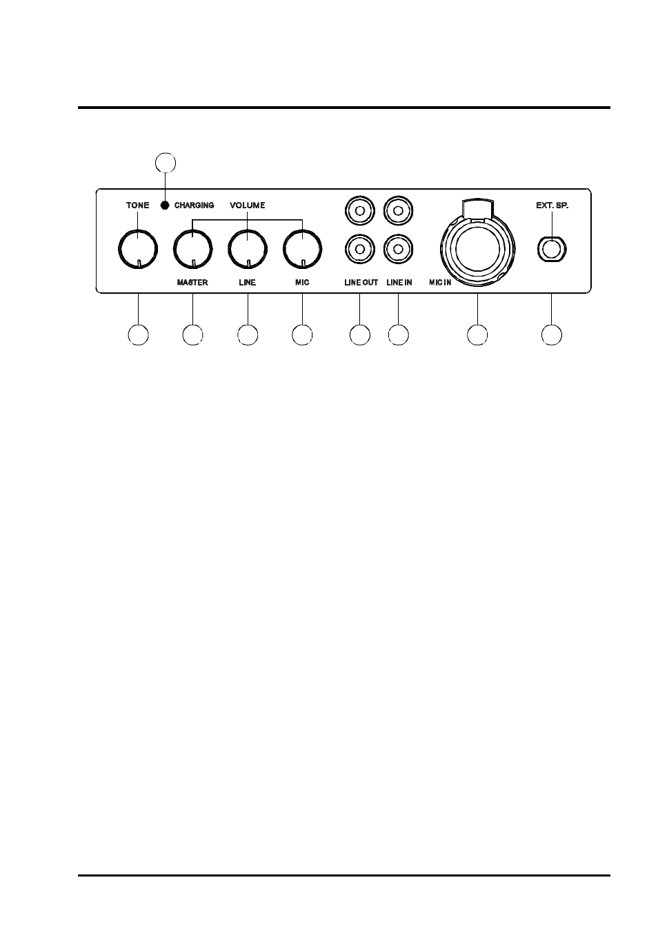
A. Control Panel
(Fig.1)
(A1) Tone Control : Turn counterclockwise to increase bass or turn clockwise to
increase treble. Set at 12 o'clock for a flat response.
(A2) Master Volume Control : Simultaneously adjusts the volume of all mixed audio
inputs.
(A3) LINE IN Volume Control: Controls the volume of the Line Socket (A6).
(A4) Mic In Volume Control : Control the volume of the wired microphone (A7).
(A5) Line Out Socket : Stereo line level audio output.
(A6) Line In Socket : Allows you use an external device with an unbalanced audio
output as an input to the MA-705.
(A7) Wired Microphone Input Socket (XLR Balanced/Phone Jack Unbalanced) : Allows
you to connect a wired microphone with either a balanced XLR or unbalanced
phone jack connector.
(A8) Extension Speaker Socket : Connects to an 8 Ohm/50W speaker.
(A9) Charging Indicator: The charging indicator flashes when the system is charging.
Flashing stops when the batteries are fully charged.
B. Optional Wireless Microphone Receiver Modules
MIPRO offers a selection of optional wireless microphone receiver modules. Each
module has unique features and you may install one or two modules in the MA-705.
1.
MA-705-VA: VHF
Receiver Module.
2.
Antenna-Diversity
MA-705-UA : UHF Antenna-Diversity Receiver Module.
WIRELESS AMPLIFIER