Installation – CIRCUTOR DHB Series User Manual
Page 8
Advertising
8
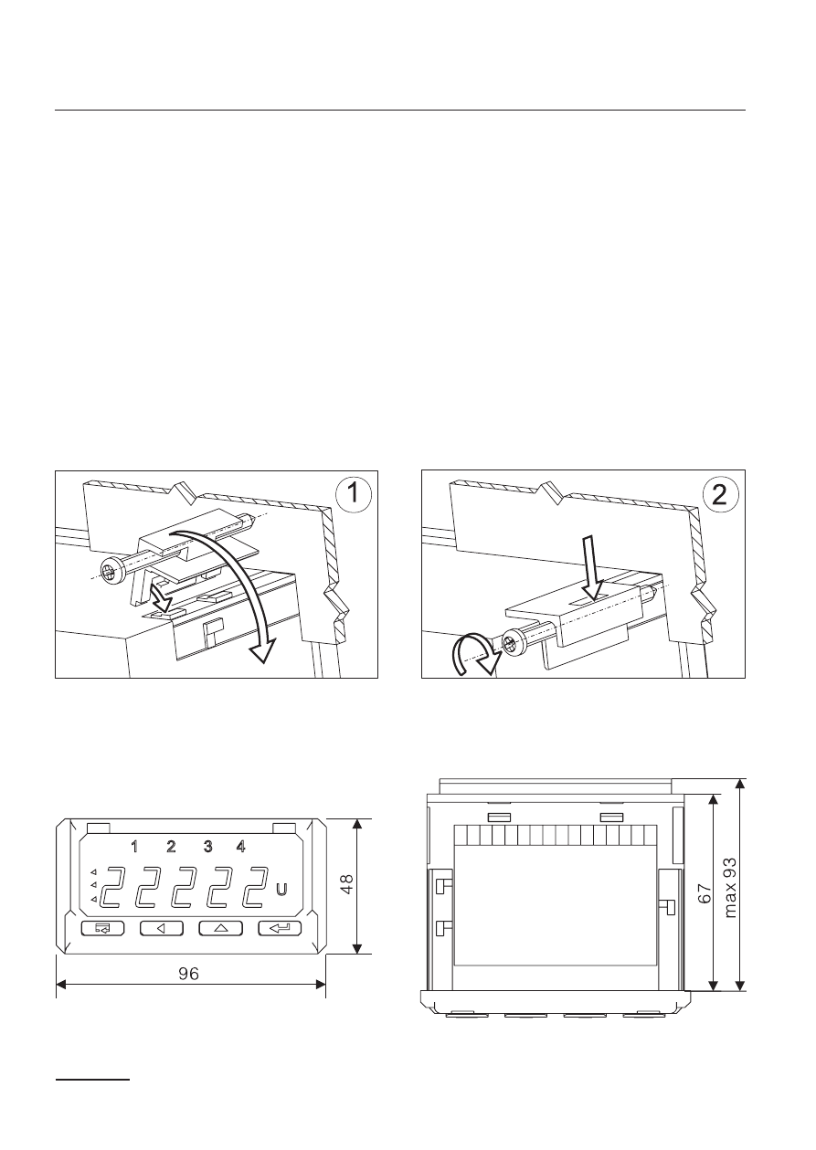
Fig. 3. Overall dimensions
Fig. 2. Meter fixing
4. INSTALLATION
The meter has separable strips with screw terminals, which enable the
connection of external wires of 2.5 mm
2
cross-section. Strips of input
signals are protected against any accidental disconnection by means
of a screw joint.
One must prepare a hole of 92
+0,6
´ 45
+0,6
mm in the panel, which the
thickness should not exceed 6 mm.
The meter is adapted to be mounted in a panel. The meter must be
introduced from the panel front with disconnected supply voltage. Be-
fore the insertion into the panel, one must check the correct placement
of the seal. After the insertion into the hole, fix the meter by means of
clamps (fig.2).
Advertising