AMETEK APG-XT User Manual
Page 27
Section 3. Operation
Tracking
25
Tracking
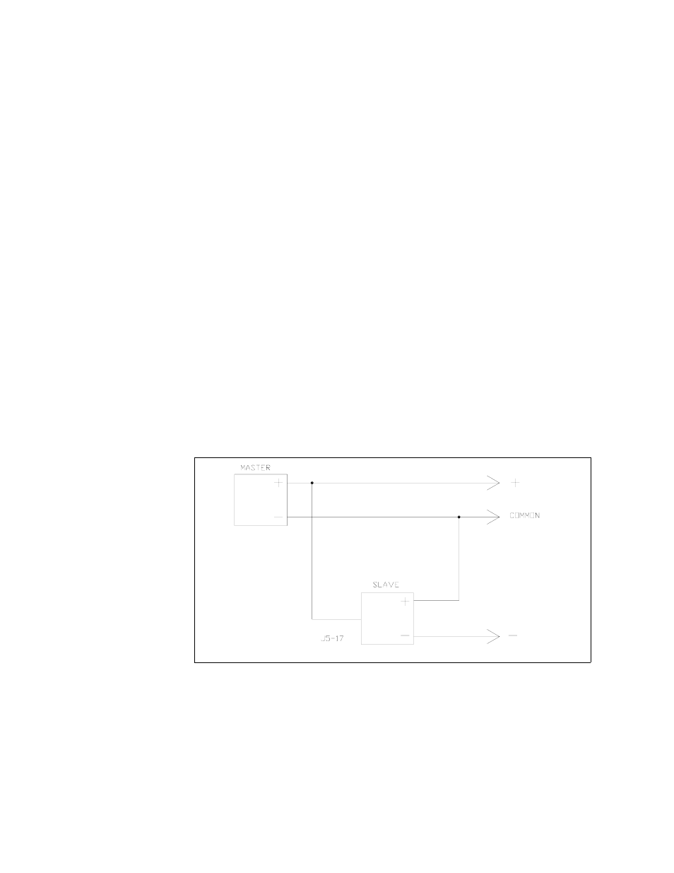
For tracking +/- outputs, use the following set-up:
•
Set slave unit rear panel switch S1-5 (remote voltage program select) and switch
S1-6 (tracking select) to ON (closed).
•
Connect master return (J5 connector pins 12, 13, or 24) to slave +OUT (J5
connector pins 10, 11, or 23).
•
Connect master +OUT (J5 connector pins 10, 11, or 23) to slave voltage program
input (J5 connector pin 17).
Notes:
1. Master/slave power supplies must have the same output ratings.
2. Set switch S2 on the slave unit's APG Interface PCB to the correct model
number (factory preset). This requires that you remove the power supply cover.
3. Slave tracking can be calibrated by adjusting the unit's offset and range
potentiometers. See “Calibration Adjustment” on page 17.
4. As the slave is referenced to the master's output, the noise and ripple on the slave
may increase. In addition, if the master's output decreases due to current limit
acting, the output voltage of the slave will follow.
Figure 3.2 Master/Slave Tracking Configuration