Communication settings and led descriptions, Usb-link technical guide 12 operator interface, Usb-link led descriptions – Auto-Zone Control Systems SS0070 USB-Link Technical Guide, Installation Instructions for the SS0070 USB-Link (Version 01D) User Manual
Page 12: Usb-link communication settings
USB-Link Technical Guide
12
Operator Interface
Communication Settings and LED Descriptions
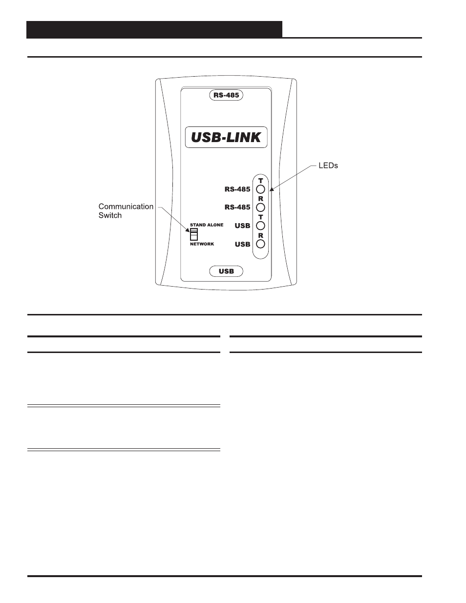
Figure 3: USB-Link Communication Switch and LEDs
USB-Link LED Descriptions
RS-485 -
Indicates communication activity between the
USB-Link and the controller(s) that the USB-Link
is connected to. When both the “T” and “R” LEDs
are
fl ashing, data is being exchanged.
USB
-
Indicates communication activity between the
USB-Link and the computer that the USB-Link
is connected to. The “T” and “R” LEDs will fl ash
only when data is sent from Prism II to the USB-
Link via USB.
USB-Link Communication Settings
The communication switch for stand alone or network mode is
found to the left of the LEDs. See Figure 3 above. To set the
communication switch, insert a pen tip to move the switch up
or down.
NOTE:
Whenever you change the communication setting
on the USB-Link, you must cycle the power to the
USB-Link by disconnecting and reconnecting the
USB power supply cable.
Stand Alone - No MiniLink or CommLink -
The slide switch
on the USB-Link should be set to “Stand Alone” when you
are trying to talk to a stand alone controller or multiple con-
trollers on a loop without a CommLink or a MiniLink wired
to the communications loop.
Network - MiniLink or CommLink connection -
The slide
switch on the USB-Link should be set to “Network” any time
there is a CommLink or MiniLink wired to the communications
loop.