Installation, Approved vent configurations – Avalon Firestyles 864 TRV GS2 Installation User Manual
Page 27
Installation
(for qualified installers only)
27
Travis Industries
4140611
100-01385
Approved Vent Configurations
Restrictor Position
Intake and exhaust restrictors are built into the appliance to adjust the flow rate of intake air and
exhaust gases. Depending upon the vent configuration, you may be required to adjust the restrictor
positions. The charts for acceptable vent configurations detail the correct vent restrictor positions.
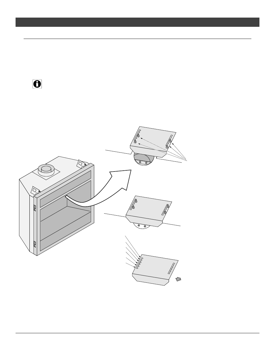
Exhaust Restrictor Adjustment
If the diffuser is required to be in position # 2, you may wish to adjust the diffuser while the exhaust
restrictor is removed.
NOTE: The restrictor is held in place with 4 screws. If using position 4, 5, or 6, remove the forward
screws. These screws may be replaced in the holes if using position 5 or 6. For position 4 the
screws holes are covered by the restrictor plate.
Loosen (or remove) these
4 screws on the exhaust
restrictor.
Slide the restrictor to the correct
restrictor position (see the illustration
below). The rear screw location
indicates restrictor position. In this
example, the restrictor is set in position
# 3. Tighten the screws to secure the
restrictor.
(closed) #6
# 5
# 4
# 3
# 2
(open - stock position) # 1
Back of Firebox
Back Wall of Firebox
Firebox Roof