Be1-cds240 solution, Figure 1-4. delta/wye transformer circuits -11, Figure 1-4. delta/wye transformer circuits – Basler Electric BE1-CDS240 General Information User Manual
Page 13
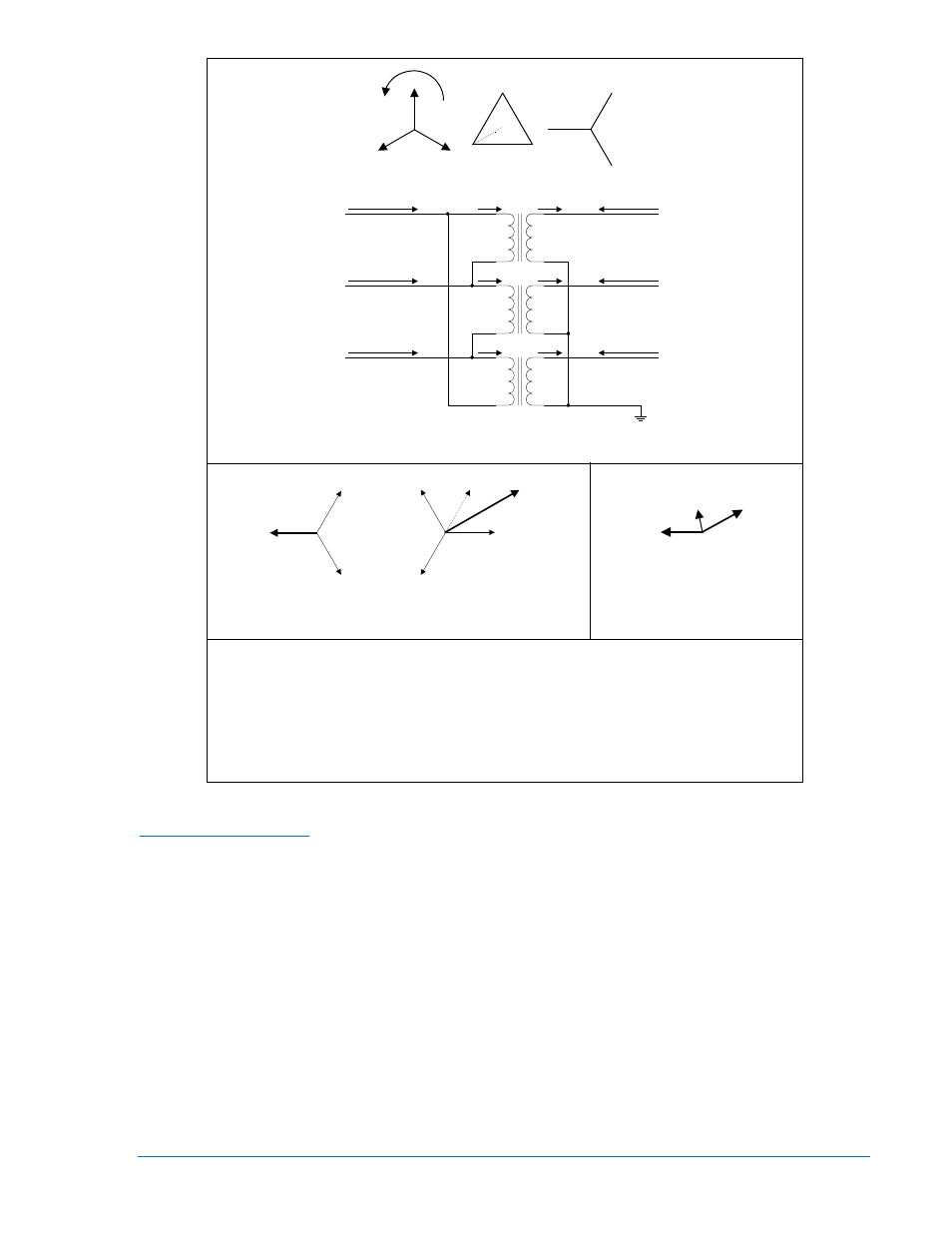
Figure 1-4. Delta/Wye Transformer Circuits
BE1-CDS240 Solution
The input currents must be combined to mimic the way they are combined in the protected power
transformer so that the currents presented to the differential protection are made up of the same
components. Traditionally, this has been done by special connection of the CTs. Figure 1-5 shows the
transformer from Figure 1-4 with the CTs connected. The wye-side CTs can be connected in delta such
that the differential protection is summing IA with Ia-Ib. The resulting two currents being seen by the
differential relay are now made up of the same components but exactly 180 out of phase with each other.
They will always sum to zero (after tap adjust for magnitude mismatch) under all conditions of balance or
unbalance except when there is a fault inside the zone of protection.
D2837-12
02-26-03
H
2
H
1
H
3
X
2
X
1
X
0
X
3
I
CD
I
C
=I
CD
-I
AD
I
c
=-I
cy
I
cy
I
b
=-I
by
I
by
I
a
=-I
ay
I
ay
I
BD
I
B
=I
BD
-I
CD
I
AD
I
A
=I
AD
-I
BD
X
0
B
C
A
H
3
H
2
H
1
X
1
X
2
X
3
I
Differential
I
a
I
A
I
a
lags I
A
by 180°+30°=210°
I
b
I
c
I
a
I
BD
I
CD
I
AD
-I
BD
I
A
=I
AD
-I
BD
Illustration A
Illustration B
Illustration C
Ib=Low side, phase B line current
I
BD
=Phase B, delta winding current
I
A
=High side, phase A line current
Ia=Low side, phase A line current
I
B
=High side, phase B line current
IC=High side, phase C line current
I
AD
=Phase A, delta winding current
I
CD
=Phase C, delta winding current
Ic=Low side, phase C line current
Ia
Y
=Phase A, wye winding current
Ib
Y
=Phase B, wye winding current
Ic
Y
=Phase C, wye winding current
9365200990 Rev M
BE1-CDS240 General Information
1-11