Besa Lighting Pahu 8 (120V Pendants) User Manual
Installation guide
INSTALLATION GUIDE
Model 1KS Series -01 (Med. Base Pendant Set 120V)
1KS.01, Rev.4 12-11
Caution: Turn off power to electrical box before installing
6695 Taylor Rd. Blacklick, OH 43004
www.besalighting.com
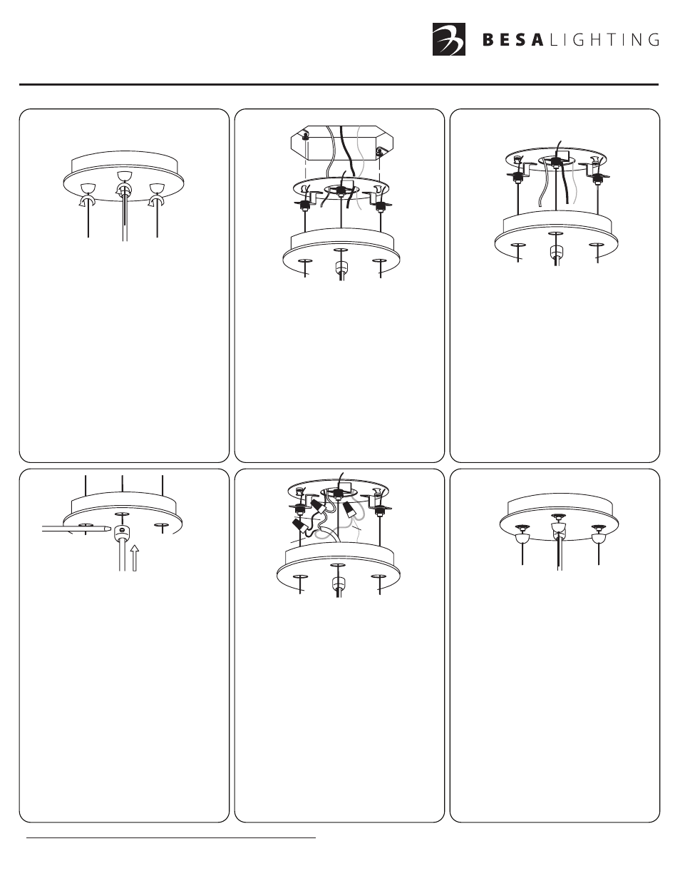
1. Carefully unpack parts. Remove
the Canopy (A) from the Mounting
Plate by unscrewing the three (3)
Retainers. Fully remove the
Retainers from the threaded
nipple, then pull the canopy
from the Mounting Plate.
A
B
2. Install the provided Mounting
Screws (C) into the Outlet Box,
leaving 1/4” of threading as shown.
Pull the House Wires from the
Outlet Box and extend through
the center opening in the Mounting
Plate (D).
C
D
Align the circular openings of
the Keyhole Slots (E) with the
Screws then push the Mounting
Plate up over the Outlet Box.
Rotate the Mounting Plate and
secure with Mounting Screws.
E
3. Shorten the three (3) cables to
the desired length by pushing
the cable up through the Cable
Retainers (F). Trim off the excess
cable length, leaving about 3”
of slack for final adjustment.
To lower the cables, push the
Cable Retainer up, which will
release the cable and allow it
to be lowered.
4. Prior to installing the canopy, the
cord length must be adjusted.
Loosen the set screw on the Strain
Relief (G), the feed the cord up
through until reaching the desired
length. Tighten the set screw until
the cord is firmly in place.
NOTE:
For a curvy cord
appearance, leave about 25%
slack for shaping of the cord
Once the cord length has
been adjusted, the cord must
be shortened above the canopy.
When shortened, insure that
there is 6” or more of wire
above the canopy.
6. Prior to replacing the canopy,
push the house wiring and
wirenuts up through the center
opening and into the Outlet Box.
Push the canopy up tight to the
ceiling as shown, then secure
with the Retainers. Do not
overtighten the retainers, as this
could make it difficult to remove.
G
F
5. Attach the the bare copper fixture
ground wire and bare (or green
striped) ground conductor from the
cord to the supply ground and secure
with provided Wire Nut Connector (H).
Connect the cord conductors from
the fixture cord to the supply
conductors with Wire Nut Connectors
(J) as shown: Cord conductor with
white stripe to white supply wire and
clear cord conductor to black supply
wire.
NOTE:
When using the clear style cord,
it is advised that the installer
confirm the polarity per
instructions on the next page.
H
Clear
White Stripe
Bare or Green Stripe
J
Replacement parts for this 120V Voltage Pendant Set are as follows:
#T1KS100-SN.01 - 100W 10’ clear cordset and 3 support cables with Nickel Hardware
For Bronze cordset, use “BR” in place ”SN”. For 15’ cordset, place “L” after metal finish.