Daktronics AB-1600-1.5,2.5 User Manual
Page 15
Introduction
1-7
1.4
Daktronics Nomenclature
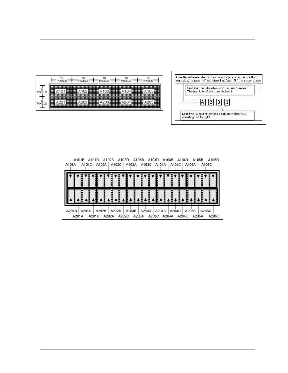
The Daktronics module numbering system assigns numbers to modules to aid in wiring and
troubleshooting. Remember, a module is two, side-by-side lens/reflector assemblies. Figure 15
illustrates how the top two rows of a large matrix display would be numbered starting from the left.
Figure 16 explains the meaning of the module numbering.
Lampbanks also have a numbering system. There are two
lampbanks mounted on the back of each lens/reflector
assembly. Therefore, there are four lampbanks per module. Figure 17 illustrates this lampbank
numbering. It uses the same first four digits as the module numbering system, but with an A, B, C or D
at the end to indicate whether it is the first, second, third or fourth lampbank on that module.
In addition, when using Daktronics drawings it may also be helpful to know the following.
“F” denotes a fuse (F1, F2, F3…)
“T” denotes a transformer (T1, T2, T3)
“TB” denotes a termination block – power or signal.
“A” denotes an assembly. These are divided according to power or signal.
Figure 15: Module Numbering (16x80 display) – Front View
Figure 16: Module Numbering Detail
Figure 17: Numbering (16x80) - Front View