Daktronics AB-1600-1.5,2.5 User Manual
Page 38
Electrical Installation
3-12
Connecting Signal to the Data
Distributor
Signal from the controller computer must first be
routed to the data distributor and then to the
column directors in the display. This signal is
routed through fiber optic cable, which should be
run through rigid, metal conduit, as opposed to
flexible conduit.
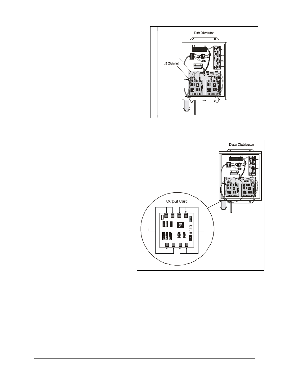
Fiber optic cable from the controller computer
connects to the data distributor receiver board at
the J5 (data in) jack. The data distributor and
the location of the J5 jack on the receiver board
are illustrated in Figure 32.
Sending Signal from the Data
Distributor to the Display
Cat-5 cable from the data distributor
must be connected to the column
directors in a display. Route the Cat-5
cable through rigid metal conduit.
Output cards in the data distributor,
Figure 33, are responsible for sending
the data signal to the column directors
through the Cat-5 cable. There can be
anywhere between two and ten output
cards in the data distributor – it depends
on sign size. They are stacked on top of
each other in pairs.
Each output card has two signal outputs,
as shown in Figure 33. Signal #1 would
be sent to one of the display’s column
directors, Figure 35, while signal #2
would be sent to another. The number of
signals a data distributor can send
depends on the number of output cards.
Each signal is sent to four jacks in case there is the need to send the same signal to multiple
displays. If sending data to a single display, only one of the four jacks on each signal output will be
used.
In Figure 33, the jacks on each signal output (signal #1 and signal #2) are labeled A, B, C or D.
The column directors within a display should all receive data from the same jack on both signal
outputs on every output card. For instance, if only one display were present, one column director
would be connected via Cat-5 cable to A on signal #1 and another would be connected via another
Cat-5 cable to A on signal #2. This would be true of every output card in the data distributor.
0
P-1
190
-01
50
S
N:
345
6
0
7-6
4-9
7 R
EV.
4
REV. 1
REV. 1
0P-
119
0-0
150
SN:
34
56
07-
64-9
7 R
EV
. 4
0
P-11
90
-01
50
S
N: 3
45
6
0
7-64
-97
RE
V.
4
L
INE
LOAD
F-5
757
687
6-98
6 SN
:98
5-858
7
U
R
567
-575
P-8
678
0P
-119
0-0
150
SN
: 34
56
07-
64-
97
REV
. 4
Data Distributor
Receiver Board
Figure 32: J5 (Data In) jack on the data distributor
receiver board
0P-
1190
-015
0
SN:
345
6
07-6
4-9
7 RE
V. 4
REV. 1
REV. 1
0
P-11
90-
0150
S
N: 3
456
0
7-64
-97
REV
. 4
0P
-119
0-0
150
SN
: 34
56
07
-64-
97 R
EV.
4
L
INE
LOAD
F-57
57
6876
-986
SN:98
5-858
7
UR
567-57
5
P-8678
0P
-119
0-01
50
SN
: 34
56
07
-64-
97 R
EV.
4
REV. 1
0
P
-
11
9
0
-0
1
5
0
S
N
:
3
4
56
0
7
-6
4
-9
7
R
EV
.
4
Signal #1
Signal #2
A
A
B
B
C
C
D
D
Figure 33: Output Card