Daktronics AB-1600-1.5,2.5 User Manual
Page 50
Maintenance & Troubleshooting
4-6
CAUTION: Make sure to use a lanyard when
removing a lens/reflector assembly from the
rear of the display. This will prevent the
lens/reflector from falling forward out of the
display.
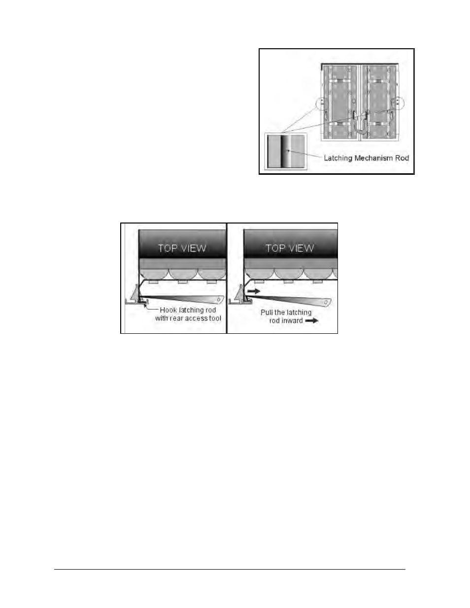
1. After removing the back sheet from the rear of
the display, find the two latching mechanisms on
either side of the back of the lens/reflector
assembly as seen in Figure 44.
2. Attach the safety lanyard. Refer to Appendix C
for additional information.
3. Use the rear access tool (found in display tool kit)
to hook and pull the latching mechanism rod in
toward the center of the lens/reflector assembly, as seen in Figure 45.
4. Repeat Step 2 to unlatch the mechanism on the other side of the lens/reflector assembly.
5. The le ns/reflector assembly can now be removed. The safety lanyard should be in place to
prevent the assembly from suddenly falling forward. Disconnect all ribbon cables and power
connectors from the lamp banks mounted on the assembly’s backside. The assembly is now
completely free of the cabinet.
Note: It takes only mild pressure to free each side of the lens/reflector assembly. Excessive force
can bend the rod.
Complete the following steps to replace or install a lens/reflector assembly in a rear
accessible display.
1. With the safety lanyard in place, the lens assembly must be passed through the opening,
rotated right side up and then pulled back into place.
2. When pulling the lens assembly into place, it should be tilted about 30 degrees so the bottom
goes in first.
3. Pull the lens assembly firmly back into place until the latches, one on each side of the frame
verticals snap into place.
Figure 44: Lens/Reflector Latching
Mechanisms (Rear-View)
Figure 45: Unlatching a lens/reflector assembly with the rear access tool