Daktronics AB-1600-1.5,2.5 User Manual
Page 46
Maintenance & Troubleshooting
4-2
4.2
Operational Summary
Reference Drawings:
Schematic, Power & Wiring220V LR.......................................................Drawing A-127375
Schematic, Power & Wiring230V LR.......................................................Drawing A-127376
Schematic, Power & Wiring240 LR .........................................................Drawing A-127377
Schematic, Power & Wiring220V DD......................................................Drawing A-127543
Schematic, Power & Wiring230V DD......................................................Drawing A-127544
Schematic, Power & Wiring240V DD......................................................Drawing A-127545
This overview summarizes the power and signal functioning of the typical 1600 series, 2.5-inch large
matrix displa y. Refer to the display schematics in Appendix B or any project specific drawings
included in Appendix A for detailed power and signal information.
There are a number of schematics in Appendix B. Use the following table as a guide in choosing the
one appropriate for this display.
In addition, the locations of the panelboards, display controller and fan control enclosure are shown in
shop drawings in Appendix B, assuming no project specific drawings are in Appendix A.
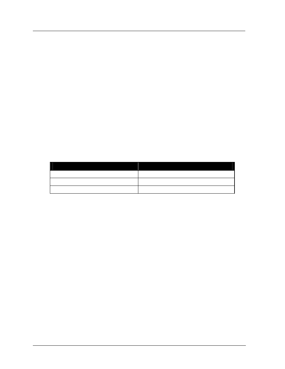
Use the following table to choose the correct shop drawing.
If the display being installed is…
Consult Section 3 shop drawing…
24 high display (all lengths)
Drawing B-114883
32 high display (all lengths)
Drawing B-114884
40 high display (all lengths)
Drawing B-114885
Power Summary
As addressed in Power Installation, incoming power terminates at the panelboard. The
panelboard is typically mounted within 20 feet of the display but may be mounted to the display
itself in special circumstances. Display grounding is the responsibility of the installer and should be
done in agreement with both Article 250 of the National Electrical Code and all local codes and
standards.
From the panelboard, power is routed to the transformers, the number of which is determined by
display size. Each transformer is individually protected by a 20-amp breaker on the primary side.
From the transformers, power is routed to the individual lampbanks on the backsides of the
lens/reflector assemblies. Each transformer is capable of powering a maximum of two modules
(eight lampbanks).
In addition, the panelboard also houses the breaker for the display controller (serial line interface).
Replace this breaker with only another of equal value.
Power to the fans is routed through the fan controller from the panelboard. If the display is blank
for 30 minutes, the display controller can flip a relay, turning off the fans and extending the life of
both the fans and the filters.