Daktronics AB-1600-1.5,2.5 User Manual
Page 51
Maintenance & Troubleshooting
4-7
There are some areas on the display where components prevent the lens assembly from passing
through the opening in the displa y. In this case, a second lens assembly above or below the first
one must be removed, creating an opening large enough for the lens assembly to pass through.
Lens assemblies must fit together tight so the weather stripping forms a good seal and prevents
water from leaking between the lens assemblies and into the display. Check the seal between the
assemblies with a 0.032” feeler gauge. Refer to Section 4.13.
4.4
Lenses
A lens is positioned in front of each lamp in the lens/reflector assembly. The lenses, along with the
reflectors, direct the light from the display. Sixty-four lenses are found in each lens/reflector assembly.
*Compete the following steps to remove a lens from a
lens/reflector assembly.
•
Carefully pry out the lens tab using the lens/lamp extractor
found in the tool kit. The lens tab is found on the top center
of the lens. Refer to Figure 46.
•
If necessary, gently press up on the louver above the lens to
aid in removal. Applying excessive force to the louver may
cause it to become deformed.
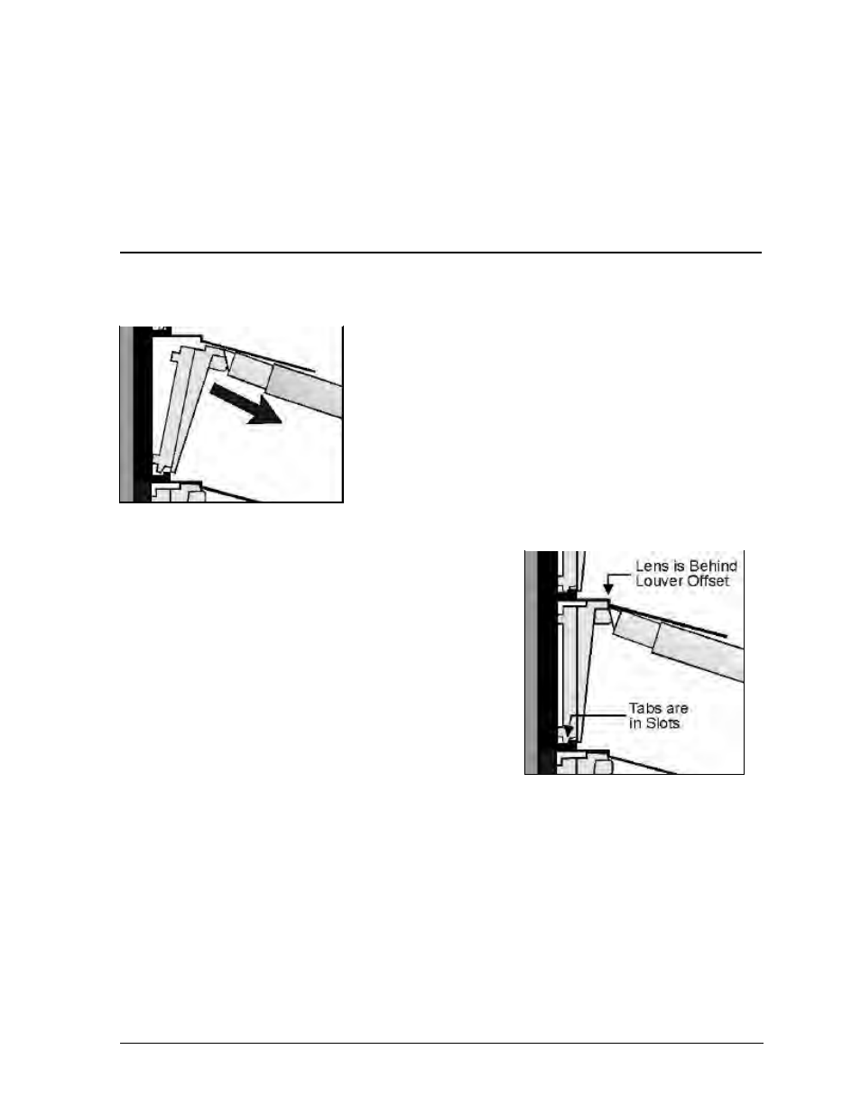
Complete the following steps and refer to Figure 47 to insert
a lens into the lens/reflector assembly.
Insert the lens’ indexing tabs into their respective slots on the
lens/reflector assembly. There is one indexing tab on the
bottom-left and bottom-right corners of the lens.
1.
Push the lens into position behind the louver offset. If
necessary, gently press up on the louver above the lens to
aid in insertion. Applying excessive force to the louver
may cause it to become deformed.
2. Verify the lens position and placement is consistent with
others in that row. If a lens looks out of position there is
likely an indexing tab not in its slot.
Figure 46: Removing a lens
Figure 47: Inserting a lens