Client (scoreboard) – Daktronics Gen VI Radio User Manual
Page 11
Setting Radio Channels
5
Client (Scoreboard)
To locate and access the receiver, refer to the service documentation for the particular
scoreboard model.
1. Power ON – the POWER indicator (green LED) illuminates.
2. After an approximately seven-second delay to allow the scoreboard to perform a
segment test, “b# C#” displays on the scoreboard (refer to Section 2.1), followed by
“US” or “EU” depending on region.
“US” – Domestic (US/Canada) radio with higher transmit power and access to
all Broadcast Groups.
“EU” – International (Europe/UK etc) radio with lower transmit power and
access to Broadcast Groups 1-4 only.
Note: Mixed radio types are not compatible.
3. The radio receiver listens for a sever on the following channels, in order:
a. B# C# - the exact channel the radio is set to via its switches
b. B# C0 – the broadcast channel
c. B0 C0 – the master broadcast channel
d. Diagnostics Channel – see Section 3.3
e. The sequence then repeats.
4. The receiver searches until a server on one of those channels is detected. The DATA
OUT indicator (red LED) will flash periodically while searching.
5. Once locked onto a server, the RADIO IN RANGE indicator (amber LED)
illuminates. The radio will remain on that channel until the server is removed,
powered down, or the client is powered down.
Note: Refer to Drawing A-1109105 (indoor) or Drawing A-1109181 (outdoor) in
Appendix A for instructions on changing the channel and broadcast groups inside the
radio receiver.
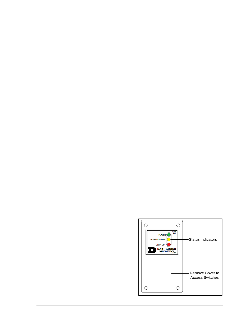
Figure 4 shows the LED indicators on the radio receiver.
POWER (green LED) –
Illuminates when power is applied
to the receiver
RADIO IN RANGE (amber LED) –
Illuminates when a server (radio-
equipped console) is active on the
receiver’s broadcast group channel
DATA OUT (red LED) – Randomly
flashes when data is being received
from a server; regularly pulses when
searching for a server
Figure 4: Radio Receiver w/ Cover