4 recommended spares, 5 tools required, 6 casing, seal housing and fastener torques – Flowserve CPXV fitted with Mark 3 ASME hydraulics User Manual
Page 26: Tools required (6.5)
CPXV with Mark 3 ASME hydraulics ENGLISH 71569291 12-14
Page 26 of 44
flowserve.com
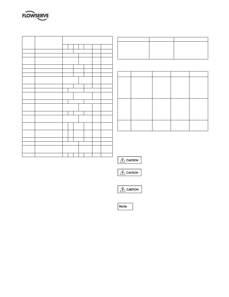
6.4 Recommended spares
(For two years operation - as per VDMA 24296)
Part
no.
Designation
Number of pumps
(including stand-by)
2 3 4 5 6/7
8/9
10(+)
2100
Shaft
1
2
3
30%
2200
Impeller
1
2
3
30%
2400.1
Shaft sleeve -
pump end
2
3
4
50%
3013
Bearing - thrust
1
2
3
4
50%
3300.1 Bearing - pump end
1
2
3
4
50%
3300.2 Bearing - lineshaft #
1
2
3
4
50%
3400.1
Shaft sleeve -
intermediate #
2
3
4
50%
3712
Bearing nut
1
2
3
4
50%
4120
Lantern halves #
1
2
3
30%
4130
Gland packing -
complete set #
2
3
4
40%
4200
Mechanical seals # 1
2
3
30%
2400.2
Sleeve -
mechanical seal #
2
3
4
50%
4305
Lip seal #
4 6
8
9
10
100%
6570.9
Shaft sleeve screw
for 3400.1 #
2
3
4
50%
4590.1 *
Pump casing
gasket
4 6
8
9
12
150%
4590.2
Discharge flange
gasket
4 6
8
9
12
150%
4610.1 O-ring impeller
4 6
8
9
12
150%
4610.2 O-ring carrier
2
3
4
50%
4610.3
O-ring mechanical
seal sleeve #
2
3
4
50%
-
Power end
-
-
-
-
-
1
2
# When required due to fitting as part of the original build specification.
6.5 Tools required
A typical range of tools that will be required to
maintain these pumps is listed below.
Readily available in standard tool kits, and dependent
on pump size
– standard SAE hand tools for ASME
wet end hydraulics:
Hand wrenches
Socket wrenches
Open ended spanners (wrenches) to suit up to
M 48 screws/nuts
Socket spanners (wrenches), up to M 48 screws
Allen keys, up to 10 mm (A/F)
Range of screwdrivers
Soft mallet
More specialized equipment:
Bearing pullers
Bearing induction heater
Dial test indicator
C-spanner (wrench) - for removing shaft nut.
(If difficulties in sourcing are encountered, consult
Flowserve.)
6.6 Casing, seal housing and fastener
torques
Fastener
Screw size
Torque Nm (lbf•ft)
All except where
otherwise stated
M8
M10
M12
M16
M20
16 (12)
25 (18)
35 (26)
80 (59)
130 (96)
Standard SAE fasteners for ASME wet end
hydraulics:
Item
Description
Group 1
Group 2
Group 3
[6572.2]
Plain bearing
carrier studs
⅜ in. –
16 Nm
(12 lbf•ft)
⅜ in. –
16 Nm
(12 lbf•ft)
½ in.
–
54 Nm
(40 lbf•ft)
½ in.
–
41 Nm
(30 lbf•ft)
[6570.1]
Casing
screws
½ in.
–
41 Nm
(30 lbf•ft)
½ in.
–
41 Nm
(30 lbf•ft)
⅝ in. –
81 Nm
(60 lbf•ft)
¾ in.
–
136 Nm
(100 lbf•ft)
⅞ in. –
217 Nm
(160 lbf•ft)
[6572.3]
Bearing cover
screws
⅜ in. –
27 Nm
(20
lbf•ft)
⅜ in. –
27 Nm
(20
lbf•ft)
½ in.
–
54 Nm
(40
lbf•ft)
Notes:
1. For non-lubricated/coated threads, add 25 % to the values
given above.
2. Gasket joint torque values are for unfilled PTFE gaskets. Other
gasket materials may require additional torque to seal.
Exceeding metal joint torque values is not recommended.
Above apply for applications below
250 ºC only and not in the range 250 ºC to 600
ºC.
Below lower values apply for
applications
in the high temperature range of 250 ºC to
600
ºC.
Non-metallic gaskets incur creep
relaxation - before commissioning the pump check
and retighten fasteners to tightening torques stated.
For the tightening sequence also refer to good
industry practice. See section 10.3, Reference 6, for
more detail.