3 valve identification, 4 threaded valve – pipe assembly, 5 flanged joint assembly – Flowserve Vogt Forged Steel Gate User Manual
Page 18
Flow Control
Vogt Valves
18
Forged Steel Gate, Globe and Check Valves
FCD VVENIM2000-02
• Inspect end connections to be sure that pipe threads and flange
faces are free from scratches, nicks, or dents.
a
CAUTION: Vogt valves are shipped with plastic threaded
or welding end protectors. During inspection for
installation, make sure these protectors have not been
mishandled and displaced into the valve interior. If so
they must be removed.
4.3 Valve Identification
All valves have a nameplate attached to the handwheel that include
the series number, size, pressure class and material. The valve
nameplate needs to be reviewed in conjunction with the installation,
maintenance, and spare parts ordering instructions in this manual.
Valves Constructed Under The European Pressure Equipment
Directive (PED)
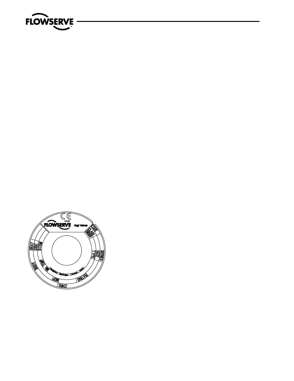
A nameplate attached to the valve (as noted in the Illustration below)
shall identify all Vogt PED Category III valves. This nameplate shall
be placed on the valve at the factory. In addition to the nameplate,
the Vogt PED valve will also have a lot tag to identify the date of
manufacture. All nameplates for Category III valves shall have the
CE-mark and shall also include the Notified Body Number.
Figure 2 – Vogt Valves PED Valve Nameplate
4.4 Threaded Valve – Pipe
Assembly
Threaded pipe joints depend on a good fit between the external and
internal pipe threads for tight sealing. Usually, a compatible soft or
viscous material is used between the assembled threads to assist
in ensuring a leak-free seal. The following installation practices are
recommended:
a) Check the threads on both the valve and the mating pipe for cor-
rect thread form and cleanliness. Be alert for any indication of an
impact that might have deformed the thread either out-of-round
or by a local indentation. Be sure no chips or grit are present.
b) Note the internal length of the threads in the valve ends and the
proximity of the valve internal seat to make sure the pipe end will
not hit the seat when assembled. If there appears to be a pos-
sibility of a problem, carefully check the pipe end thread to make
sure there is no extended straight portion beyond the standard
tapered section.
c) Apply an appropriate thread tape or thread compound to the
external pipe threads except when dry seal threading is speci-
fied. Avoid getting the thread tape or thread compound into the
internal flow area.
d) Use care to align the threads at the point of assembly. Tapered
pipe threads are inherently a loose fit at entry. Substantial
wrenching force should not be applied until it is apparent that
the threads are properly engaged.
e) Assemble the joint wrench-tight. The wrench on the valve should
be on the valve end into which the pipe is being threaded.
a
CAUTION: Because there is no clear limit on the torque
that may be developed in a tapered thread joint, it is
possible to damage the valves or piping by applying
excessive twisting forces through the body of the valve.
If at all possible a wrench should be used on the same
end of the valve to which the pipe is being threaded into.
This way the torque load will not be applied throughout
the valve body.
f) Repeat the process at the second valve end. Again, apply the
wrench at end of the valve to which the pipe is being assembled.
4.5 Flanged Joint Assembly
Flanged joints depend on compressive deformation of the gasket
material between the facing flange surfaces for tight sealing. The
bolting must provide the mechanical force necessary to maintain
the compressive stresses on the gasket, as well as resist the normal
pressure forces tending to separate the joint. It should be recognized
that with “brute force” alignment of misaligned flanges, sufficient
bolting force may not be available to sustain the required gasket
loading and to resist the load caused by the pressure separating
force, resulting in a joint leakage problem. The following practices
should be observed for satisfactory flange joint make-up:
a) Check the mating flange facings. Do not attempt to assemble
the flanges if a condition is found which might cause leakage