Led indicators, Stroke calibration using the quick-cal button – Flowserve Logix 1200e LGAIM0044 User Manual
Page 17
Flowserve Corporation, Valtek Control Products, Tel. USA 801 489 8611
44-17
WARNING: If rotating in wrong direction, seri-
ous damage will occur to the positioner and/or
linkage. Check air action and stroke direction
carefully.
LED Indicators
The Logix 1200e has three LED indicators that are vis-
ible through a window in the main cover. Only one LED
will blink at any given time. Each LED has a different
color to convey basic information about the positioner
status. Green indicates that the positioner is operating
normally. Yellow indicates that a ‘customer defined
limit’ or ‘alert’ has been reached. Red indicates that an
error condition exists. The HART hand held communi-
cator, ValTalk or SoftTools PC software must be used
to determine the specific reason for a yellow or red
LED status.
During stroke and actuator calibration, no LED will
blink. After calibration is complete, the green LED indi-
cates that the calibration was completed successfully.
If the yellow or red LED blinks after a calibration pro-
cess, a warning or error was detected and the HART
communication to the device must be used to identify
the specific calibration error.
NOTE: If the LED indicator changes from green to yel-
low after a calibration process, the user may have set
a warning limit (position alert, cycle counter alert,
etc.). Use HART communications to monitor status.
Stroke Calibration using the Quick-Cal Button
For cases when the HART hand held communicator,
ValTalk or SoftTools PC software is not available, the
Logix 1200e has a Quick-Cal feature that performs a
stroke calibration and allows basic operation of the
positioner. The Quick-Cal routine applies full supply
pressure to the upper and lower mechanical limits to
determine the valve stroke. Valve systems without
mechanical stops must use the ValTalk or SoftTools
software to manually calibrate the valve.
WARNING: The calibration routines are only to be
used on systems which have mechanical stops.
The calibration routines apply full supply pressure
to determine stroke length and may cause damage
to the valve, actuator or positioner.
NOTE: The Quick-Cal operation retains all previously
configured information except for the three DIP switch
settings and stroke parameters. The settings of
ATO/ATC, Linear/Rotary, Linear/Custom and stroke
parameters are overridden and rest to the DIP switch
settings when the Quick-Cal button is used. If the
device is being installed for the first time, factory
default parameters are used.
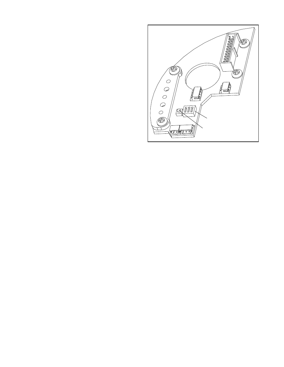
The Quick-Cal button and DIP switch settings are
located on the collector board inside the main housing
chamber as shown in Figure 17.
WARNING: Accessing this function requires
removal of the main cover. The user must take all
precautions if this operation is performed in explo-
sion-proof areas.
Make the appropriate configuration settings, using the
DIP switches on the collector board. ATO/ATC selects
air-to-open or air-to-close (this is determined by the
mechanical tubing of the actuator). The
LIN_VALV/ROT_VALV button allows the user to select
linear or rotary feedback linkage. The LIN_VALV
switch enables the feedback potentiometer to utilize
the entire resolution through a maximum of 60
degrees rotation (45 degrees is typical). The
ROT_VALV switch increases the rotation of the poten-
tiometer up to 105 degrees (90 degrees is typical).
Thus a long stroke sliding stem valve may require this
dip switch to be set on ROT_VALV if the stroke rotates
the feedback potentiometer more than 60 degrees.
The LIN/CUSTOM option allows selection of linear or
custom control characterization. If Custom is
selected, the positioner activates custom character-
ization. If the device is being installed for the first time,
the default custom characterization is equal percent.
However, if a custom curve has been previously
loaded, the previous curve will be used. The DIP
switch settings are only read after the Quick-Cal but-
ton is pressed for 5 seconds; otherwise, the settings
do not have any effect. The DIP switch settings will
override any previous configuration done using HART
communications. Press the Quick-Cal button for five to
ten seconds. If the button is released before five sec-
onds have elapsed, no action will be taken. After
approximately five seconds, the positioner will begin a
Figure 17: Quick-Cal Button
Quick-Cal DIP Switch
Quick-Cal Button