Positioner operation, Detailed sequence of positioner operations – Flowserve Logix 1200e LGAIM0044 User Manual
Page 4
44-4
Flowserve Corporation, Valtek Control Products, Tel. USA 801 489 8611
.
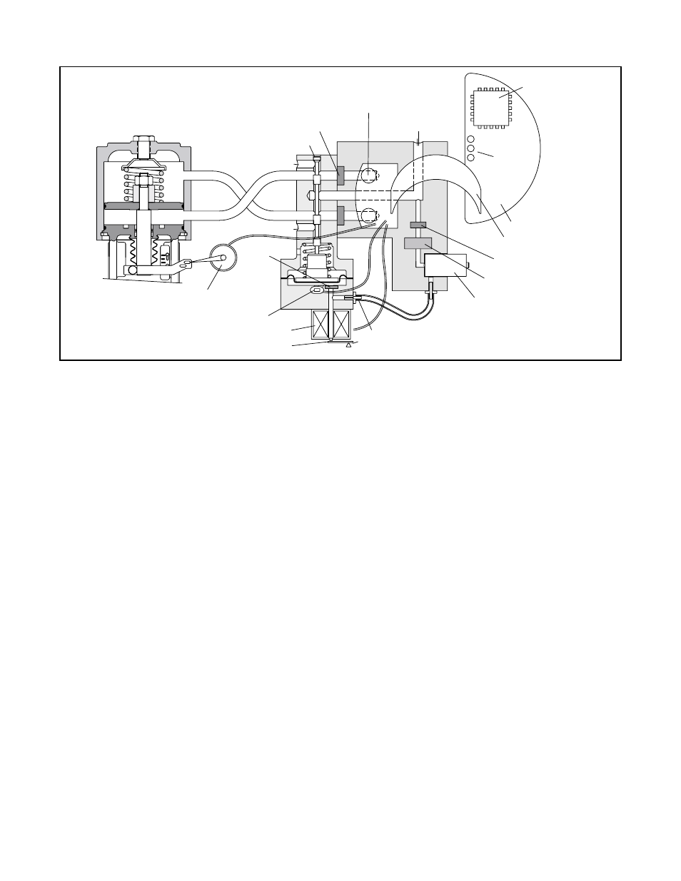
Positioner Operation
The Logix 1200e positioner is an electric feedback
instrument. Figure 1 shows a Logix 1200e positioner
installed on a double-acting actuator for air-to-open
action. Positioning is based on a balance of two sig-
nals: one proportional to the command input signal
and the other proportional to the valve stem position.
The supply pressure for the positioner pressure modu-
lator is tapped off the main supply. Next it passes
through an internal pressure regulator that regulates it
to approximately 22 psig. The air then passes through
an orifice that restricts the flow and air consumption.
The pressure modulator further controls the air to
6-10 psig, when operating current is applied, using a
spring-diaphragm flapper that is attracted by an elec-
tromagnet to a nozzle. A temperature compensated
hall effect sensor mounted on a circuit board senses
the spool valve position. The hall effect sensor and cir-
cuitry create an inner feedback loop, which determines
how much current to send to the electromagnet for a
desired spool valve position. The electro-magnet in
the feedback loop varies the nozzle-flapper spacing,
which regulates the output pressure to 6-10 psig, pro-
portional to the digital position algorithm.
When the command and stem position signals are
equal, the system will be in equilibrium and the valve
stem will be in the position called for by the command
signal. If these opposing signals are not equal, the
spool valve will move up (or down) and, by means of
the pressure modulator, change output pressures and
flow rate. This will cause the actuator piston to move
until the signal of the position sensor equalizes with
the command signal.
Detailed Sequence of Positioner
Operations
The detailed sequence of positioner operations is as
follows: An increase in the command signal causes
the modulator pressure to increase, pushing the spool
assembly upward from its equilibrium position. This
opens the spool valve ports, supplying air to Output 1
and exhausting air from Output 2. This causes the
actuator piston to move upward.
The upward motion of the piston is transmitted back to
the positioner through the stem position feedback link-
age, changing proportionally to the valve stem posi-
tion. The piston continues to stroke upward until the
stem position signal of the sensor increases suffi-
ciently to counter the signal being sent to the control
algorithm. At this point, the spool is at its equilibrium
position as the pressures in the cylinder stabilize and
the air flow to the actuator decreases. The positioner
will then make small null adjustments to fine-tune the
desired position and compensate for changes in
dynamic loading.
A decrease in the command signal reverses the
described actions, causing a proportional downward
movement of the actuator piston and stem.
Figure 1: Logix 1200e Digital Positioner Schematic
O
H
all E
ffect Sensor
E
lectro magnetic Coil
Nozzle
Flapper
Digital Position
Algorithm
Spool Valve
Flame Arrestors
Collector Board
Pressure Sensor
Air Supply
LED
Display
Orifice
Exhaust
OUTPUT 1
OUTPUT 2
Exhaust
Flame
Arrestor
Stem Position Sensor
Air-to-open
Configuration
Main PCB Tray
Ribbon Cable
Flame Arrestor
Filter
Regulator