1 command 48 data – Flowserve MX HART Field Unit User Manual
Page 24
MX/QX HART Field Unit FCD LMENIM2340-00 – 1/14
24
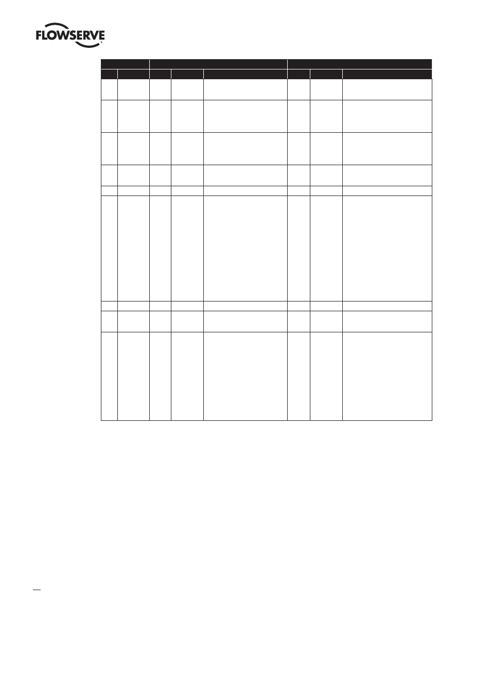
Command
Request Data Bytes
Response Data Bytes
No.
Description
Byte
Format
Description
Byte
Format
Description
16
Read Final
Assembly
Number
0-2
Unsigned-24
Final Assembly Number
17
Write Message
0-5
6-17
18-20
Packed
Packed
Date
Tag
Descriptor used by the master for record
keeping
A date code used by the master for record
keeping (E.G. Last or Next Calibration Date)
0-23
Packed
Message String
18
Write Tag,
Descriptor,
Date
0-5
6-17
18-20
Packed
Packed
Date
Tag
Descriptor used by the master for record
keeping
A date code used by the master for record
keeping (E.G. Last or Next Calibration Date)
0-5
6-17
18-20
Packed
Packed
Date
Tag
Descriptor
Date Code
19
Write Final
Assembly
Number
0-2
Usigned-24
Final Assembly Number
0-2
Usigned-24
Final Assembly Number
20
Read Long Tag
0-31
Latin-1
Long Tag
21
Read Unique
Identifier
Associated
With Long Tag
0-31
Latin-1
Long Tag
0
1-2
3
4
5
6
7
7
8
9-11
12
13
14-15
16
17-18
19-20
21
Unsigned-8
Enum
Unsigned-8
Unsigned-8
Unsigned-8
Unsigned-8
Unsigned-5
Enum
Bits
Unsigned-24
Unsigned-8
Unsigned-8
Unsigned-16
Bits
Enum
Enum
Enum
“254”
Expanded Device Type = 0x3008
Min. number of request preambles = 5
HART Protocol Major Rev. = 7
Device Rev. Level
Software Rev. Level
(5 MSB) Hardware Rev. Level
(3 LSB) Physical Signaling Code=0
Device Flag Assignment = 0
Device ID (unique for given device type)
Min. number of response preambles=5
Max. number of device variables = 5
Configuration Change Counter
Extended Field Device Status: 0=OK,
1=Maintenance req’d, 2=Device Alert
Manufacturer Identification Code = 0x0030
Private Label Distributor Code = 0x0030
Device Profile = 1
22
Write Long Tag
0-31
Latin-1
Long Tag
0-31
Latin-1
Long Tag
38
Reset
Configuration
Changed Flag
0-1
Usigned-16
Configuration Changed Counter
3
0-1
Usigned-16
Configuration Changed Counter
3
48
Read
Additional
Device Status
0-5
6
7
8
9
10
11
12
13
14-21
4
Bits
Bits
Bits
Bits
Bits
Bits
Bits
Bits
Bits
Bits
Device-Specific Status 0
Extended Device Status
Device Operating Mode
Standardized Status 0
Standardized Status 1
Analog Channel Saturated
Standardized Status 2
Standardizes Status 3
Analog Channel Fixed
Device-Specific Status 1
0-5
6
7
8
9
10
11
12
13
14-21
Bits
Bits
Bits
Bits
Bits
Bits
Bits
Bits
Bits
Bits
Device-Specific Status 0
Hardware Faults bytes 0-3
Main Board Status bytes 4-5
Extended Device Status
Device Operating Mode
Standardized Status 0
Standardized Status 1
Analog Channel Saturated
Standardized Status 2
Standardizes Status 3
Analog Channel Fixed
Device-Specific Status 1
Hardware Warnings bytes 14-17
Device Status bytes 18-21
Not Used bytes 22-24)
4
3.5.1.1 Command 48 Data
The “More Status Available” bit in Device Status will be set if any bit in the following command 48 data is set, which
previously was not set:
• DeviceSpecificStatus_0 (bytes 0-3 only – hardware faults)
• ExtendedDeviceStatus
• StandardizedStatus
• AnalogChannelSaturated
• AnalogChannelFixed
• DeviceSpecificStatus_1 (bytes 14-17 – hardware warnings)
NOTE: DeviceSpecificStatus_0, bytes 4-5 (main board status information) is provided only for additional
information but these bits will not trigger More Status Available, as these are not considered faults or warnings.
DeviceSpecificStatus_1, bytes 18-21 (device status information) is provided only for additional information but these
bits will not trigger More Status Available, as these are not considered faults or warnings.
3. Upon receiving this command the device shall compare the counter value received in this command with the device’s current value. If they do not match then the device
will return Response Code 9 “configuration change counter mismatch” and not reset the configuration change counter.
4. HART specification allows up to 25 bytes for this command. However, it also states that “the response data bytes returned are truncated after the last status byte
supported by the Field Device”. Therefore we only return 22 bytes of data in our response. If the master sends a request with more than 22 bytes of data, our device will
still respond, but the extra bytes beyond those supported will be ignored