Jetway Computer J7F2 User Manual
Page 17
13
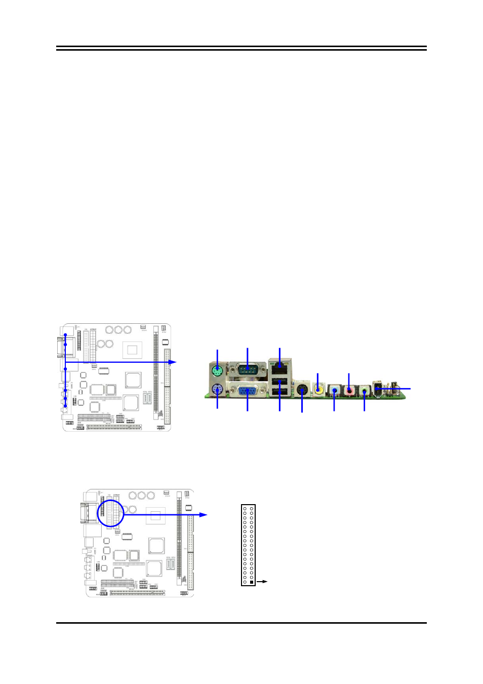
(3) USB Port connector: UL1
The connectors are 4-pins connector that connect USB devices to the system board,
and standard RJ45 connector for Network supports 10/100 BASE-T transfer rate.
(4) Serial Port Connector (9-pin female): COM1
Serial Port connector is a 9-pin D-Subminiature connector. The On-board Serial Port
can be disabled through the BIOS SETUP. Please refer to Chapter 3 “INTEGRATED
PERIPHERALS SETUP” section for more detail information.
(5) VGA Connector (15-pin female): VGA
VGA Connector is a 15-pin D-Subminiature Receptacle connector.
This connector is for connection Monitor and System to display.
(6) TV-Out Connector: S-Video/ RCA
The S-Video/RCA Connector is for S-Video/Composite TV-Out function
RCA is setting for Composite TV-Out connector when JP3 setting 1-2 closed
RCA is setting for SPDIF-Out connector when JP3 setting 2-3 closed
(7) Audio Connector: (Line-Out/ Line-IN/ MIC)
This Connector are 3 phone Jack for LINE-OUT/ LINE-IN/ MIC.
Line-out :
Audio output to speaker
Line-In :
Audio input to Audio controller
MIC :
Microphone
Connector
(8) 1394 Port1 Connector: 1394
(9) Floppy drive Connector (34-pin block): FDD
This connector supports the provided floppy drive ribbon cable. After connecting the
single plug end to motherboard, connect the two plugs at other end to the floppy drives.
Pin 1
Floppy Drive Connector
(10) Primary IDE Connector (40-pin block): IDE1
PS/2
MOUSE
PS/2
Keyboard
MIC
RCA
LINE OUT
USB
VGA
1394
SVIDEO
LINE IN
COM1 LAN